You can find an index to all my articles by clicking this text
I have been very busy last months. Not only do I have a full time job, train for an upcoming sports event (four day marches) and a 'pilgrimage' to Santiago de Compostela (a 200 mile walk), I also have spend a lot of time working with the ESP32.
This resulted in a book (my second). It is called ESP32 uitgelegd which means ESP32 explained. It is in Dutch and the English version will get a different title and is what I am working on now.
So sorry guys. The rest of this post is in Dutch.
ESP32 uitgelegd.
![]()
De trouwe volgers van dit weblog weten dat ik niet veel aandacht heb besteed aan de ESP32. Slechts een paar web-logs gaan over deze wonder-chip. Dat wil niet zeggen dat ik er niet intensief mee bezig ben geweest. Maanden uitzoekwerk, opzetten van breadboard projecten en het programmeren van voorbeelden heeft geleid tot het boek met de titel: ESP32 uitgelegd.
Het is een beginners boek. En natuurlijk volledig in het Nederlands !!
In tegenstelling tot veel van mijn verhalen op mijn weblog zijn alle programma's en voorbeelden in C++ (Arduino taal) geschreven.
Het boek begint met het installeren van de Arduino software. Dan volgen het installeren van de ESP32 componenten voor Arduino, het installeren van libraries en een korte inleiding tot programmeren.
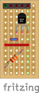
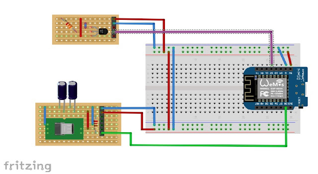
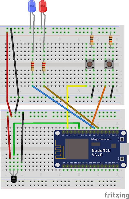
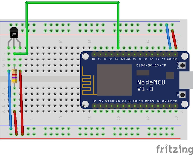
Daarna volgen hoofdstukken die je leren met allerlei sensoren en weergevers (actuators) te werken. De schema's zijn allemaal op een breadboard uitgevoerd en in de praktijk getest waarna ze in Fritzing zijn getekend voor weergave in het boek.
Het boek is geen leerboek maar om praktijkervaring op te doen eindigd elk hoofdstuk met de beschrijving van een oefening die je zelf kunt doen met de opgedane kennis uit dat hoofdstuk.
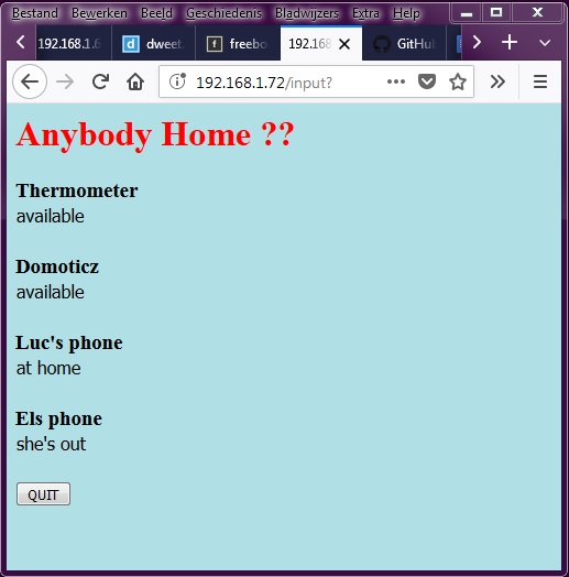
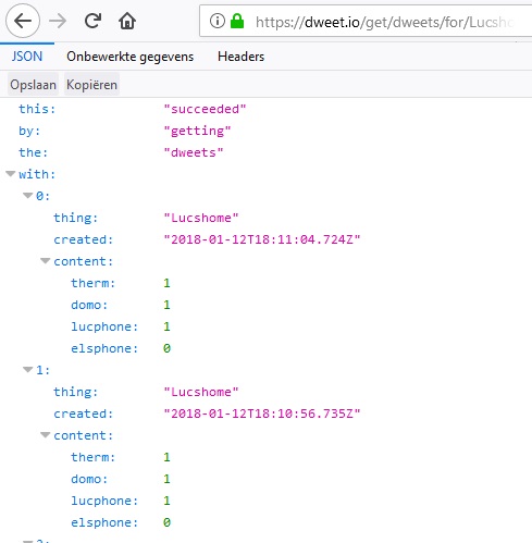
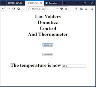
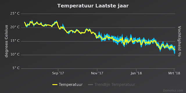
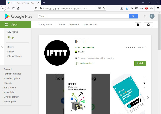
Uiteraard ontbreekt het sturen van sensoren via een zelfgebouwde website niet. De ESP32 heeft immers niet voor niets Wifi. Maar ook Thingspeak en IFTTT komen aan bod zodat je de opgedane kennis makkelijk kunt gebruiken bij het werken in de 'cloud'.
Het laatste hoofdstuk geeft je ongeveer 30 ideetjes voor het zelf bouwen van projecten die je zeker kunt verwezenlijken met behulp van alle voorbeelden in het boek.
Het is dus een echt praktijkboek.
Je hoeft de volgorde van het boek niet aan te houden. Als je na hoofdstuk 8 denkt "ik wil met sensor zus of zo aan de slag" dan ga je gewoon naar dat hoofdstuk toe. Het kan zijn dat je dan wat achtergrond info mist, maar die kun je dan weer makkelijk terugvinden door de verwijzingen naar de betreffende hoofdstukken te volgen.
Om de prijs zo gunstig mogelijk te houden, zodat het voor jong en oud bereikbaar is, zijn alle afbeeldingen in zwart-wit. Daardoor kan het boek voor de lage prijs van 19,95 verkocht worden en is het toch maar liefst 368 pagina's dik !!!
Het boek geeft je ook een lijst van Nederlandse elektronica leveranciers zodat je niet 3 weken of meer hoeft te wachten op onderdelen uit verre landen.
Een aantal van de sensoren en technieken worden ook op dit weblog besproken maar er zijn duidelijke verschillen. In de eerste plaats zijn niet alle ESP8266 libraries geschikt voor de ESP32. En op mijn weblog zijn veel programma's in ESPBasic uitgevoerd terwijl in dit boek alle programma's in de meer universele C++ taal zijn uitgevoerd. Dat komt omdat mijn weblog vaak een specifiek probleem aanpakt terwijl het boek in meer algemene termen spreekt waardoor je de beschrijvingen breder kunt inzetten.
Mijn vorige boek schreef ik bijna 25 jaar geleden en daar werden er 20.000 (ja twintig duizend) van verkoht: https://www.boekenwebsite.nl/computers-software/praktijkboek-voor-de-commodore-64
Eens kijken of jullie dat aantal voorbij gaan.......;)
ESP32 Uitgelegd is te koop (of te bestellen) bij alle fysieke boekhandels en alle online boekhandels zoals:
Boekenbestellen
Donner
Libris boekhandels
Bruna
Bookaroo
Athenaum Boekhandel
bol.com
Er zijn 33 hoofdstukken:
Hoofdstuk 1
Voor wie is dit boek bedoeld
Introductie
Over de auteur
Hoofdstuk 2
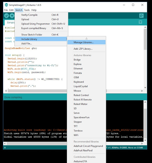
Het Installeren van de Arduino IDE
Installeren van het ESP32
Het gebruik van de IDE
Hoofdstuk 3
Het installeren van libraries
Installeren door middel van de library manager
Installeren van ZIP libraries
Handmatig installeren van Libraries
Eerste gebruik van libraries
Hoofdstuk 4
ESP32 Pin aansluitingen
Hoofdstuk 5
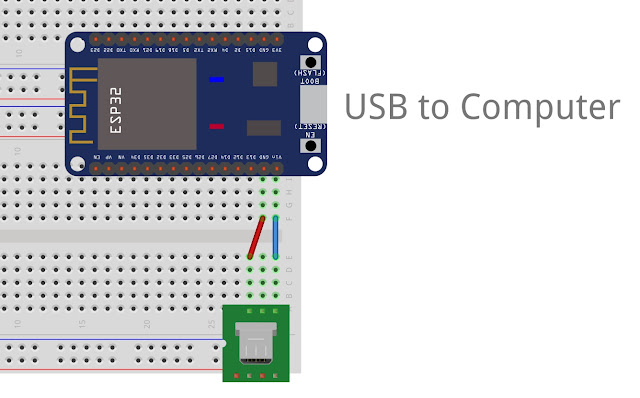
ESP op een breadboard
Hoofdstuk 6
Korte inleiding voor het werken met een breadbord
Hoofdstuk 7
Voeding
USB breadboard connector
Batterij voeding
Externe voeding
Hoofdstuk 8
Basiskennis programmeren
Hoofdstuk 9
De druktoets
Hoofdstuk 10
De Led
Oefening
Hoofdstuk 11
Dimmen van leds met PWM.
Oefening
Hoofdstuk 12
Dallas DS18B20 digitale thermometer
Installeren van libraries
Opzetten van de hardware
De eerste test
Temperatuur alarm
Oefening
Hoofdstuk 13
LDR voor het meten van licht
Test programma
Een praktisch voorbeeld
Oefening
Hoofdstuk 14
Potmeter
Hoe sluit je een potmeter aan
Potmeter test programma
We maken een dimmer
Hoofdstuk 15
Servo Motor
Breadboard met servo
De eerste servo test
Servo met een potmeter
Servo met druktoetsen
Oefening
Hoofdstuk 16
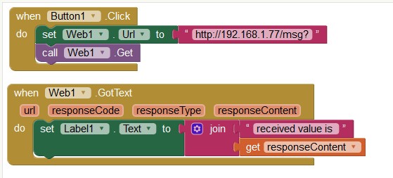
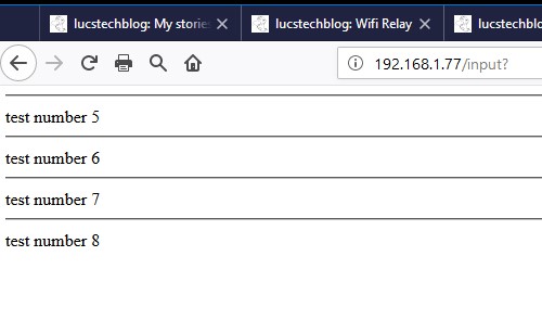
Informatie op een webpagina weergeven
Achtergrond informatie over webpagina's
De webpagina
Breadboard opbouw
Je eerste webserver
Buttons op je webpagina
CSS voor het opsmukken van depagina
Oefeningen
Hoofdstuk 17
Meer Kracht
Het programma
Hoofdstuk 18
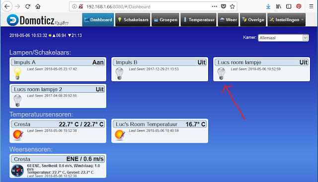
Krachtstroom met een relais
Relais aan en uitschakelen
Nachtlampje
Oefening
Werken met 230Volt
Hoofdstuk 19
Touch Sensor
Gebruik van de Touch pinnen
Een aanraakgevoelige lamp
Oefening
Hoofdstuk 20
Stuur een motor aan
Geef je planten water als het nodig is
Oefening
Hoofdstuk 21
IFTTT
Aanmelden bij IFTTT
Stap een: zoek de sleutel
Stap twee: zet notifications aan op je telefoon
Stap drie: de ESP32 kant
Oefening
Hoofdstuk 22
Neopixels
Hardware eisen
De eerste test
Neopixel kleuren
Thermometer met led indicatie
Gooi de dobbelsteen
Oefening
Hoofdstuk 23
Gebruik een H-brug voor het aansturen van een motor
Elektronische oplossing
Breadboard opstelling
Het H-Brug programma
Sneller en langzamer
Meer power
Oefening
Hoofdstuk 24
PIR bewegingsmelder
Het programma
Hoe te gebruiken
Oefening
Hoofdstuk 25
Beweging detecteren met de RCWL-0516 Radar
Programma voor bewegingsdetectie met de radar
De RCWL-0516 in gebruik nemen
Oefening
Hoofdstuk 26
Beweging met een tril sensor
De Software
Oefeningen
Hoofdstuk 27
Tilt Sensor
Oefening
Hoofdstuk 28
Interrupts
Interrupt programma
Hoofdstuk 29
Laat je gegevens zien
TM1637
TM1637 aansluiten op een breadboard
Aansturen van de TM1637
Het programma
Oefening voor TM1637
Hoofdstuk 30
Oled Display
Breadboard Library
Programmeren van de SSD1306
De Oled library commando's
Hoofdstuk 31
Thingspeak: zet je gegevens in de Cloud
Wat is een Cloud gebaseerd IOT platform
Thingspeak
Thermometer gegevens naar Thingspeak sturen
Het programma
Extra Thingspeak mogelijkheden
Privacy
Hoofdstuk 32
Ideeën
Hoofdstuk 33
Waar vind je onderdelen
Hoofdstuk 34
Waar vind je meer informatie
Hoofdstuk 35
Zelf aan de slag
Veel leesplezier
en tot de volgende keer
Luc Volders
I have been very busy last months. Not only do I have a full time job, train for an upcoming sports event (four day marches) and a 'pilgrimage' to Santiago de Compostela (a 200 mile walk), I also have spend a lot of time working with the ESP32.
This resulted in a book (my second). It is called ESP32 uitgelegd which means ESP32 explained. It is in Dutch and the English version will get a different title and is what I am working on now.
So sorry guys. The rest of this post is in Dutch.
ESP32 uitgelegd.
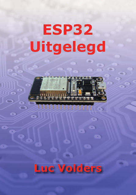
De trouwe volgers van dit weblog weten dat ik niet veel aandacht heb besteed aan de ESP32. Slechts een paar web-logs gaan over deze wonder-chip. Dat wil niet zeggen dat ik er niet intensief mee bezig ben geweest. Maanden uitzoekwerk, opzetten van breadboard projecten en het programmeren van voorbeelden heeft geleid tot het boek met de titel: ESP32 uitgelegd.
Het is een beginners boek. En natuurlijk volledig in het Nederlands !!
In tegenstelling tot veel van mijn verhalen op mijn weblog zijn alle programma's en voorbeelden in C++ (Arduino taal) geschreven.
Het boek begint met het installeren van de Arduino software. Dan volgen het installeren van de ESP32 componenten voor Arduino, het installeren van libraries en een korte inleiding tot programmeren.
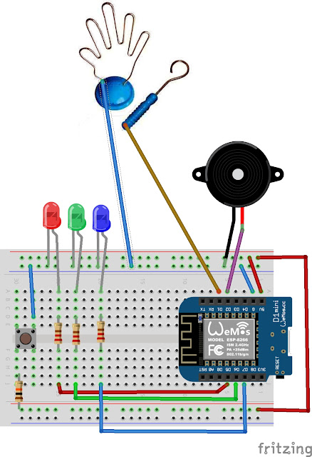
Daarna volgen hoofdstukken die je leren met allerlei sensoren en weergevers (actuators) te werken. De schema's zijn allemaal op een breadboard uitgevoerd en in de praktijk getest waarna ze in Fritzing zijn getekend voor weergave in het boek.
Het boek is geen leerboek maar om praktijkervaring op te doen eindigd elk hoofdstuk met de beschrijving van een oefening die je zelf kunt doen met de opgedane kennis uit dat hoofdstuk.
Uiteraard ontbreekt het sturen van sensoren via een zelfgebouwde website niet. De ESP32 heeft immers niet voor niets Wifi. Maar ook Thingspeak en IFTTT komen aan bod zodat je de opgedane kennis makkelijk kunt gebruiken bij het werken in de 'cloud'.
Het laatste hoofdstuk geeft je ongeveer 30 ideetjes voor het zelf bouwen van projecten die je zeker kunt verwezenlijken met behulp van alle voorbeelden in het boek.
Het is dus een echt praktijkboek.
Je hoeft de volgorde van het boek niet aan te houden. Als je na hoofdstuk 8 denkt "ik wil met sensor zus of zo aan de slag" dan ga je gewoon naar dat hoofdstuk toe. Het kan zijn dat je dan wat achtergrond info mist, maar die kun je dan weer makkelijk terugvinden door de verwijzingen naar de betreffende hoofdstukken te volgen.
Om de prijs zo gunstig mogelijk te houden, zodat het voor jong en oud bereikbaar is, zijn alle afbeeldingen in zwart-wit. Daardoor kan het boek voor de lage prijs van 19,95 verkocht worden en is het toch maar liefst 368 pagina's dik !!!
Het boek geeft je ook een lijst van Nederlandse elektronica leveranciers zodat je niet 3 weken of meer hoeft te wachten op onderdelen uit verre landen.
Een aantal van de sensoren en technieken worden ook op dit weblog besproken maar er zijn duidelijke verschillen. In de eerste plaats zijn niet alle ESP8266 libraries geschikt voor de ESP32. En op mijn weblog zijn veel programma's in ESPBasic uitgevoerd terwijl in dit boek alle programma's in de meer universele C++ taal zijn uitgevoerd. Dat komt omdat mijn weblog vaak een specifiek probleem aanpakt terwijl het boek in meer algemene termen spreekt waardoor je de beschrijvingen breder kunt inzetten.
Mijn vorige boek schreef ik bijna 25 jaar geleden en daar werden er 20.000 (ja twintig duizend) van verkoht: https://www.boekenwebsite.nl/computers-software/praktijkboek-voor-de-commodore-64
Eens kijken of jullie dat aantal voorbij gaan.......;)
ESP32 Uitgelegd is te koop (of te bestellen) bij alle fysieke boekhandels en alle online boekhandels zoals:
Boekenbestellen
Donner
Libris boekhandels
Bruna
Bookaroo
Athenaum Boekhandel
bol.com
Er zijn 33 hoofdstukken:
Hoofdstuk 1
Voor wie is dit boek bedoeld
Introductie
Over de auteur
Hoofdstuk 2
Het Installeren van de Arduino IDE
Installeren van het ESP32
Het gebruik van de IDE
Hoofdstuk 3
Het installeren van libraries
Installeren door middel van de library manager
Installeren van ZIP libraries
Handmatig installeren van Libraries
Eerste gebruik van libraries
Hoofdstuk 4
ESP32 Pin aansluitingen
Hoofdstuk 5
ESP op een breadboard
Hoofdstuk 6
Korte inleiding voor het werken met een breadbord
Hoofdstuk 7
Voeding
USB breadboard connector
Batterij voeding
Externe voeding
Hoofdstuk 8
Basiskennis programmeren
Hoofdstuk 9
De druktoets
Hoofdstuk 10
De Led
Oefening
Hoofdstuk 11
Dimmen van leds met PWM.
Oefening
Hoofdstuk 12
Dallas DS18B20 digitale thermometer
Installeren van libraries
Opzetten van de hardware
De eerste test
Temperatuur alarm
Oefening
Hoofdstuk 13
LDR voor het meten van licht
Test programma
Een praktisch voorbeeld
Oefening
Hoofdstuk 14
Potmeter
Hoe sluit je een potmeter aan
Potmeter test programma
We maken een dimmer
Hoofdstuk 15
Servo Motor
Breadboard met servo
De eerste servo test
Servo met een potmeter
Servo met druktoetsen
Oefening
Hoofdstuk 16
Informatie op een webpagina weergeven
Achtergrond informatie over webpagina's
De webpagina
Breadboard opbouw
Je eerste webserver
Buttons op je webpagina
CSS voor het opsmukken van depagina
Oefeningen
Hoofdstuk 17
Meer Kracht
Het programma
Hoofdstuk 18
Krachtstroom met een relais
Relais aan en uitschakelen
Nachtlampje
Oefening
Werken met 230Volt
Hoofdstuk 19
Touch Sensor
Gebruik van de Touch pinnen
Een aanraakgevoelige lamp
Oefening
Hoofdstuk 20
Stuur een motor aan
Geef je planten water als het nodig is
Oefening
Hoofdstuk 21
IFTTT
Aanmelden bij IFTTT
Stap een: zoek de sleutel
Stap twee: zet notifications aan op je telefoon
Stap drie: de ESP32 kant
Oefening
Hoofdstuk 22
Neopixels
Hardware eisen
De eerste test
Neopixel kleuren
Thermometer met led indicatie
Gooi de dobbelsteen
Oefening
Hoofdstuk 23
Gebruik een H-brug voor het aansturen van een motor
Elektronische oplossing
Breadboard opstelling
Het H-Brug programma
Sneller en langzamer
Meer power
Oefening
Hoofdstuk 24
PIR bewegingsmelder
Het programma
Hoe te gebruiken
Oefening
Hoofdstuk 25
Beweging detecteren met de RCWL-0516 Radar
Programma voor bewegingsdetectie met de radar
De RCWL-0516 in gebruik nemen
Oefening
Hoofdstuk 26
Beweging met een tril sensor
De Software
Oefeningen
Hoofdstuk 27
Tilt Sensor
Oefening
Hoofdstuk 28
Interrupts
Interrupt programma
Hoofdstuk 29
Laat je gegevens zien
TM1637
TM1637 aansluiten op een breadboard
Aansturen van de TM1637
Het programma
Oefening voor TM1637
Hoofdstuk 30
Oled Display
Breadboard Library
Programmeren van de SSD1306
De Oled library commando's
Hoofdstuk 31
Thingspeak: zet je gegevens in de Cloud
Wat is een Cloud gebaseerd IOT platform
Thingspeak
Thermometer gegevens naar Thingspeak sturen
Het programma
Extra Thingspeak mogelijkheden
Privacy
Hoofdstuk 32
Ideeën
Hoofdstuk 33
Waar vind je onderdelen
Hoofdstuk 34
Waar vind je meer informatie
Hoofdstuk 35
Zelf aan de slag
Veel leesplezier
en tot de volgende keer
Luc Volders