For an index of all my stories click this text
This story tells about an alarm for paintings, But do not be set off by that. You can use the same alarm for doors that open, drawers and cookie jars.
As you might know by now, my girlfriend paints and often has expositions.
![]()
Due to the new and utterly stupid privacy laws in the Netherlands I had to blur out the faces from this photo.
At this moment she has an exposition in a gallery that shares its place with the local library. Nothing wrong with that, because it attracts more people. There is however a small problem and that is security. The building has security, the paintings are insured. However there is always a chance that something happens as the gallery is not manned all the time while the library is.
So I decided to design an alarm system for the paintings.
The idea
I wanted to be able to send a notification to my phone and that of some other people when a painting is agitated or moved. To do this I used several techniques and parts which have been covered in previous stories. It all comes together here.
First the movement detection. I am going to use the SW18010P vibration sensor for that. You can find the details about this sensor in this story:http://lucstechblog.blogspot.com/2018/05/vibration-detection.html
Next I am using an ESP8266 and I am going to program it in ESP-Basic. Find an introduction about ESP-Basic here: http://lucstechblog.blogspot.nl/2017/03/back-to-basic-basic-language-on-esp8266.html
The ESP is not going to do much. It just sits there and waits till agitation or movement is detected. I can not use a wall mounted power outlet. So I have to feed it with batteries. To use as less power as is possible I am going to use Deepsleep. Find details about Deepsleep here: https://lucstechblog.blogspot.com/2018/07/esp-power-reduction-withn-deepsleep.html
Next step is to send the information to mine and others phones. As Mit's App inventor has no push notification detection until now I am going to use IFTTT for this. You can find detailed information about IFTTT in this story (which has a link to the other stories about IFTTT): https://lucstechblog.blogspot.nl/2017/09/ifttt-4-send-notification-to-my-phone.html
And then there is a housing needed. The frame of the paintings is less then 2 cm thick. So I needed to design a housing that would fit into the frame and yet holds batteries and the perfboard.
Last but not least. The location has free internet that can be used by everyone. That is just what I need for this alarm to work.
The hardware.
I am going for a minimalistic design here. There has nothing to be done except detecting a movement and sending a message. So an ESP-01 will do the trick.
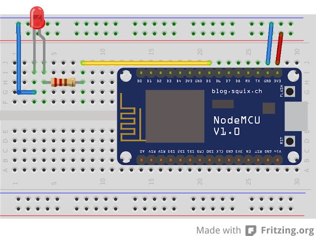
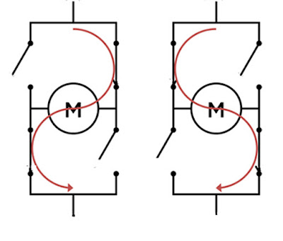
From the Deepsleep article (read it by clicking here https://lucstechblog.blogspot.com/2018/07/esp-power-reduction-withn-deepsleep.html you will know that we can put the ESP8266 into Deepsleep and it can be woken by connecting RST (reset) to ground. We are going to use the second schematic from that article here. However we are going to modify it a bit as we do not need the led we used in the test-setup.
![]()
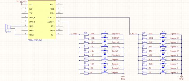
As you can see I attached the SW18010P directly to ground and the RESET pin of the ESP. To make sure the Reset pin only gets connected to Ground when needed I attached a pull-up resistor 10K to the VCC and the Reset pin. So reset will be high all the time until vibration is detected and that attaches it to Ground which wakens the ESP.
![]()
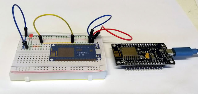
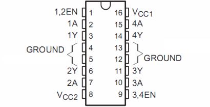
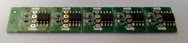
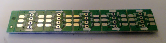
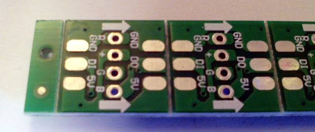
And here you can see the Stripboard version. you are looking at the soldering side. The components are in real life at the back-side.
The ESP is at the top and the antenna is at the top.
![]()
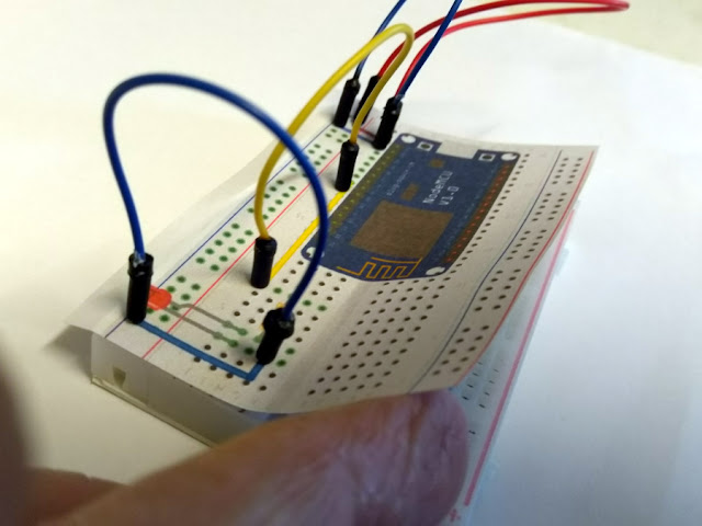
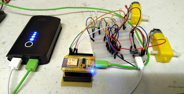
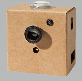
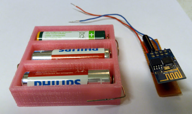
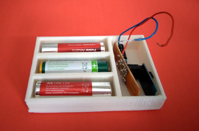
This is how it looks in real life.
What I did in this prototype is to solder the SW18010P thight against the stripboard. In my next version the SW18010P will be floating above the stripboard. I leave the leads longer and therefore there will be more space between the stripbaord and the sensor which makes it more sensitive.
Power
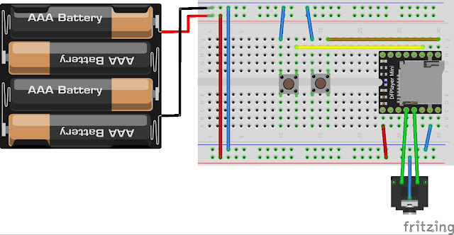
As the ESP01 is in Deepsleep it will consume very little power and therefore I can use batteries. 3 AA-type batteries will supply the power. Just like they did with the rain-sensor (read that story by clicking here).
![]()
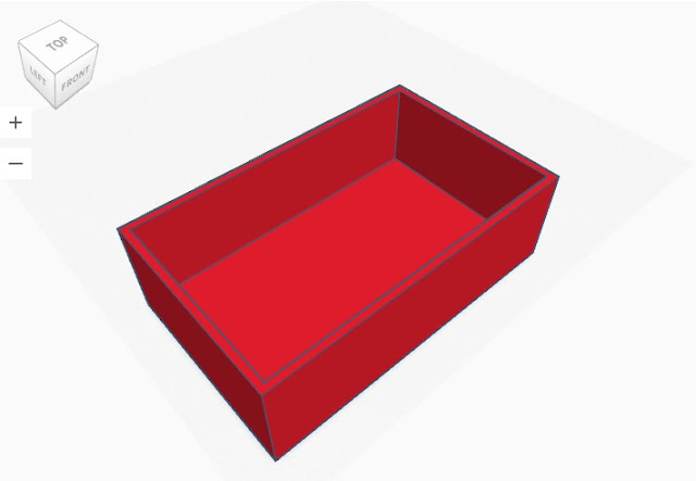
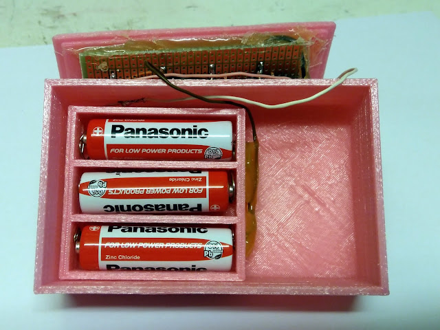
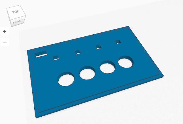
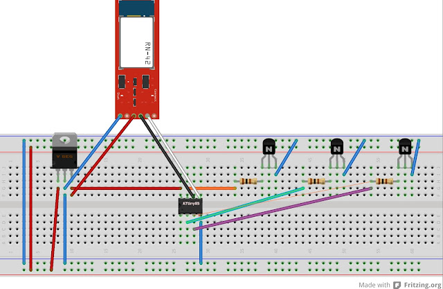
The battery case I am using is just 1.6 mm high which neatly fits into the painting frame.
![]()
The stripboard has even less height and it's length just fits within the width of the battery case. The only thing we have to do is to expand the battery case and adapt it so the stripboard fits within.
![]()
The ESP-Basic Program
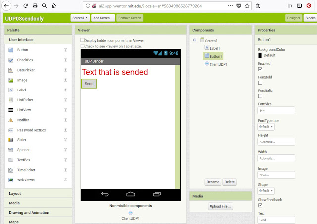
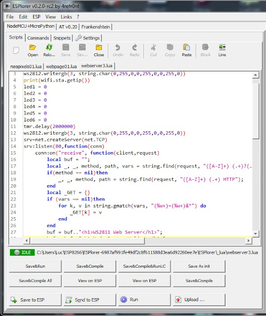
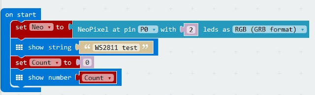
Programming the ESP in ESP-Basic is done with an on-screen editor in your web-browser which makes programming and editing very comfortable. Again: read the basics (pun intended) about ESP-Basic programming here: http://lucstechblog.blogspot.nl/2017/03/back-to-basic-basic-language-on-esp8266.html
The program is very straightforward:
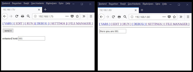
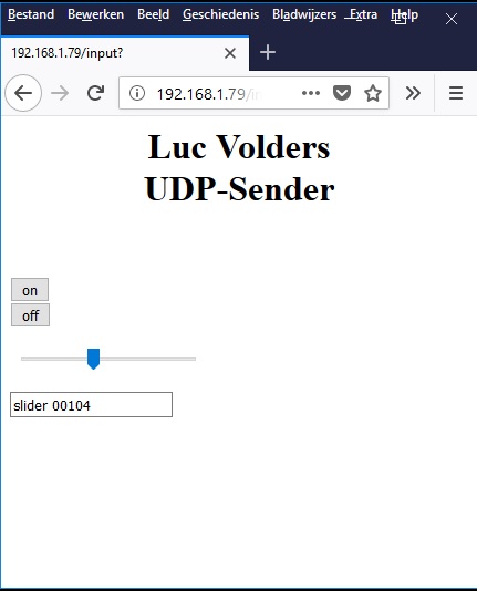
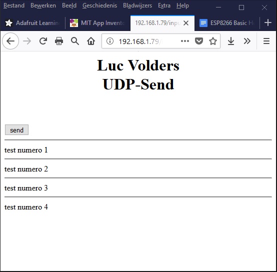
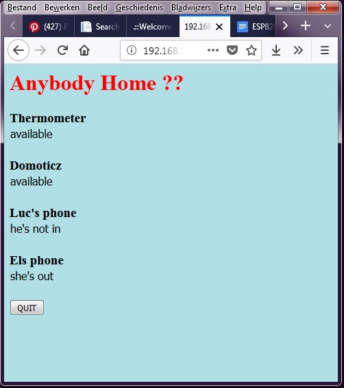
No fancy webpage. Just a button to start the sleep function and a button to stop the program.
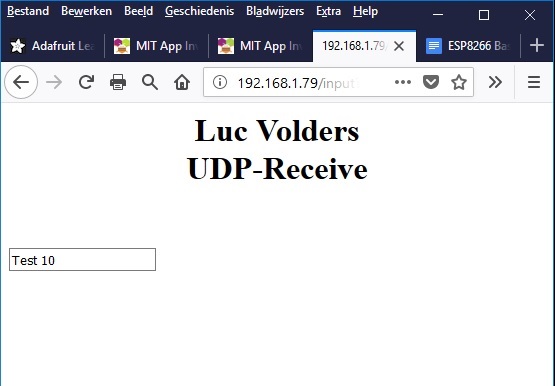
What happens when you power the ESP01 up for the first time is that it sends a notification through IFTTT. This makes sure that everything works as intended and you have an internet connection. Now you can mount the ESP in the frame.
![]()
Then press the "go to sleep" button
The ESP enters Deepsleep mode for an undefined time (sleep 0). When the painting vibrates the sensor will connect Ground to the Reset pin of the ESP01 and the ESP will awake and start the default.bas program.
![]()
Just make sure in the SETTINGS page that default.bas wil automatically run when the ESP is booted. So the cycle just repeats.
IFTTT
I have written several stories about IFTTT which I suggest you read them all. Here are the links:
https://lucstechblog.blogspot.nl/2017/04/ifttt-if-this-then-that.html
https://lucstechblog.blogspot.nl/2017/05/ifttt-part-2-maker-channel.html
https://lucstechblog.blogspot.nl/2017/05/ifttt-part-3-basic-alert-over-ifttt.html
https://lucstechblog.blogspot.nl/2017/09/ifttt-4-send-notification-to-my-phone.html
![]()
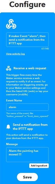
Start with making a webhook (the IF section) and link it to a notification (the THEN section).
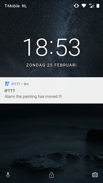
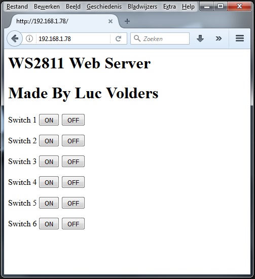
The notification
![]()
Here you can see what happens on my Android Phone when vibration is detected.
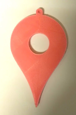
If you want a copy of the STL files of the casing for 3D printing or adjusting for your own needs just send me an email.
Till next time
Have fun !!
Luc Volders
This story tells about an alarm for paintings, But do not be set off by that. You can use the same alarm for doors that open, drawers and cookie jars.
As you might know by now, my girlfriend paints and often has expositions.

Due to the new and utterly stupid privacy laws in the Netherlands I had to blur out the faces from this photo.
At this moment she has an exposition in a gallery that shares its place with the local library. Nothing wrong with that, because it attracts more people. There is however a small problem and that is security. The building has security, the paintings are insured. However there is always a chance that something happens as the gallery is not manned all the time while the library is.
So I decided to design an alarm system for the paintings.
The idea
I wanted to be able to send a notification to my phone and that of some other people when a painting is agitated or moved. To do this I used several techniques and parts which have been covered in previous stories. It all comes together here.
First the movement detection. I am going to use the SW18010P vibration sensor for that. You can find the details about this sensor in this story:http://lucstechblog.blogspot.com/2018/05/vibration-detection.html
Next I am using an ESP8266 and I am going to program it in ESP-Basic. Find an introduction about ESP-Basic here: http://lucstechblog.blogspot.nl/2017/03/back-to-basic-basic-language-on-esp8266.html
The ESP is not going to do much. It just sits there and waits till agitation or movement is detected. I can not use a wall mounted power outlet. So I have to feed it with batteries. To use as less power as is possible I am going to use Deepsleep. Find details about Deepsleep here: https://lucstechblog.blogspot.com/2018/07/esp-power-reduction-withn-deepsleep.html
Next step is to send the information to mine and others phones. As Mit's App inventor has no push notification detection until now I am going to use IFTTT for this. You can find detailed information about IFTTT in this story (which has a link to the other stories about IFTTT): https://lucstechblog.blogspot.nl/2017/09/ifttt-4-send-notification-to-my-phone.html
And then there is a housing needed. The frame of the paintings is less then 2 cm thick. So I needed to design a housing that would fit into the frame and yet holds batteries and the perfboard.
Last but not least. The location has free internet that can be used by everyone. That is just what I need for this alarm to work.
The hardware.
I am going for a minimalistic design here. There has nothing to be done except detecting a movement and sending a message. So an ESP-01 will do the trick.
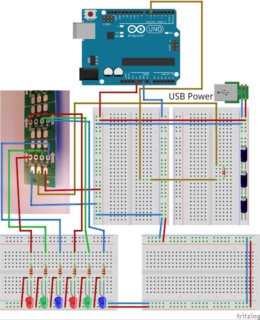
From the Deepsleep article (read it by clicking here https://lucstechblog.blogspot.com/2018/07/esp-power-reduction-withn-deepsleep.html you will know that we can put the ESP8266 into Deepsleep and it can be woken by connecting RST (reset) to ground. We are going to use the second schematic from that article here. However we are going to modify it a bit as we do not need the led we used in the test-setup.
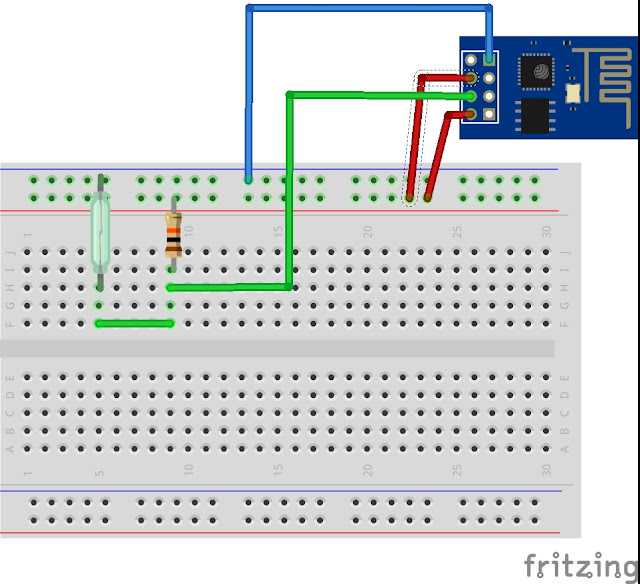
As you can see I attached the SW18010P directly to ground and the RESET pin of the ESP. To make sure the Reset pin only gets connected to Ground when needed I attached a pull-up resistor 10K to the VCC and the Reset pin. So reset will be high all the time until vibration is detected and that attaches it to Ground which wakens the ESP.
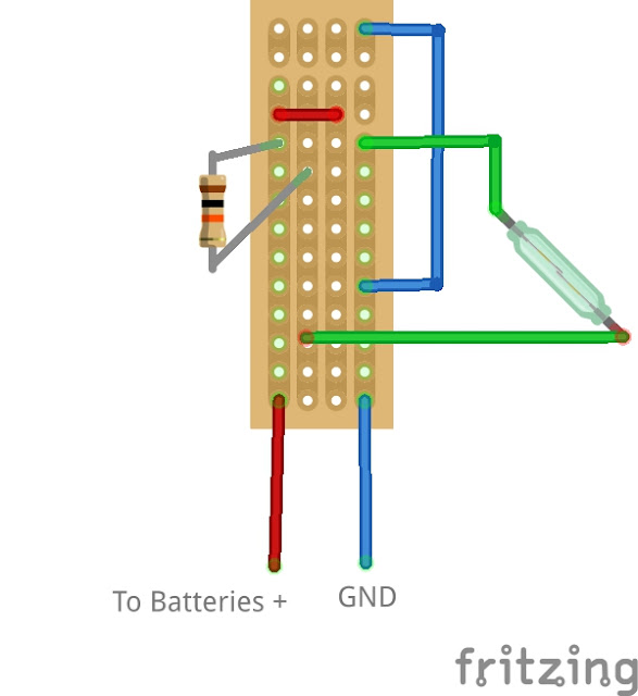
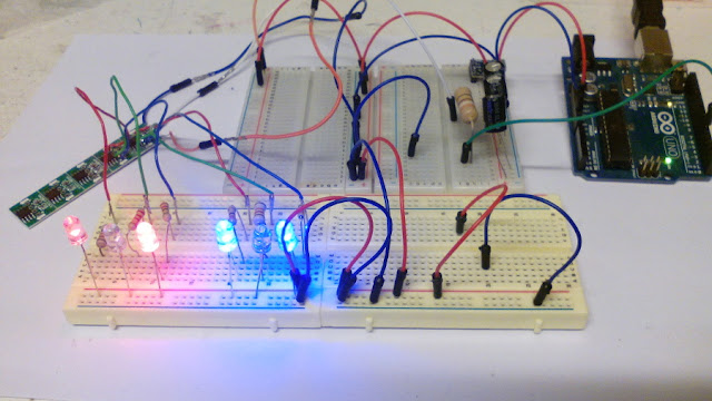
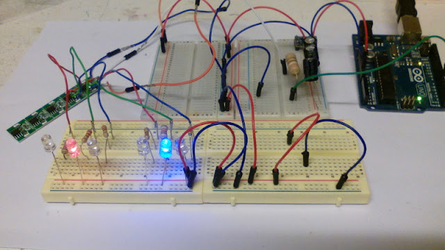
And here you can see the Stripboard version. you are looking at the soldering side. The components are in real life at the back-side.
The ESP is at the top and the antenna is at the top.

This is how it looks in real life.
What I did in this prototype is to solder the SW18010P thight against the stripboard. In my next version the SW18010P will be floating above the stripboard. I leave the leads longer and therefore there will be more space between the stripbaord and the sensor which makes it more sensitive.
Power
As the ESP01 is in Deepsleep it will consume very little power and therefore I can use batteries. 3 AA-type batteries will supply the power. Just like they did with the rain-sensor (read that story by clicking here).
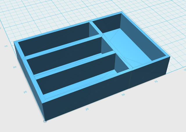
The battery case I am using is just 1.6 mm high which neatly fits into the painting frame.
The stripboard has even less height and it's length just fits within the width of the battery case. The only thing we have to do is to expand the battery case and adapt it so the stripboard fits within.
The ESP-Basic Program
Programming the ESP in ESP-Basic is done with an on-screen editor in your web-browser which makes programming and editing very comfortable. Again: read the basics (pun intended) about ESP-Basic programming here: http://lucstechblog.blogspot.nl/2017/03/back-to-basic-basic-language-on-esp8266.html
The program is very straightforward:
cls
wprint"I am awake"
wprintwget("maker.ifttt.com/trigger/alarm/with/key/PUT-YOUR-KEY-HERE")
wprint"<br>"
button"go to sleep",[sleep]
wprint"<br>"
button"stop",[stop]
wait

[sleep]
cls
wprint"sleeping"
sleep0
wait

[stop]
end
No fancy webpage. Just a button to start the sleep function and a button to stop the program.
What happens when you power the ESP01 up for the first time is that it sends a notification through IFTTT. This makes sure that everything works as intended and you have an internet connection. Now you can mount the ESP in the frame.

Then press the "go to sleep" button
The ESP enters Deepsleep mode for an undefined time (sleep 0). When the painting vibrates the sensor will connect Ground to the Reset pin of the ESP01 and the ESP will awake and start the default.bas program.
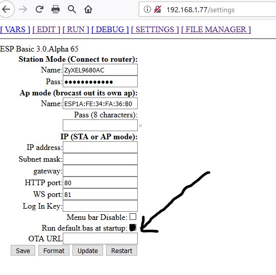
Just make sure in the SETTINGS page that default.bas wil automatically run when the ESP is booted. So the cycle just repeats.
IFTTT
I have written several stories about IFTTT which I suggest you read them all. Here are the links:
https://lucstechblog.blogspot.nl/2017/04/ifttt-if-this-then-that.html
https://lucstechblog.blogspot.nl/2017/05/ifttt-part-2-maker-channel.html
https://lucstechblog.blogspot.nl/2017/05/ifttt-part-3-basic-alert-over-ifttt.html
https://lucstechblog.blogspot.nl/2017/09/ifttt-4-send-notification-to-my-phone.html
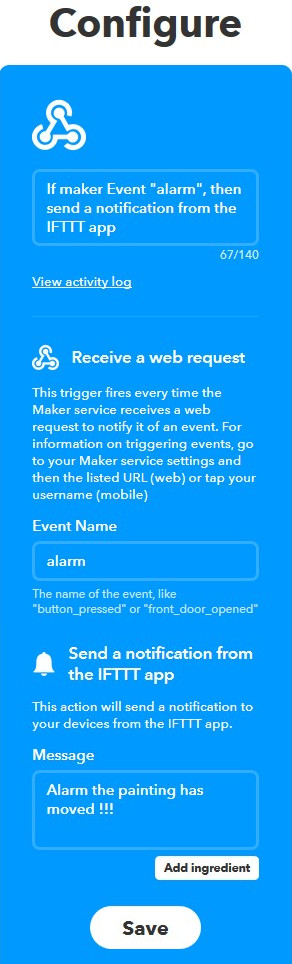
Start with making a webhook (the IF section) and link it to a notification (the THEN section).
The notification

Here you can see what happens on my Android Phone when vibration is detected.
If you want a copy of the STL files of the casing for 3D printing or adjusting for your own needs just send me an email.
Till next time
Have fun !!
Luc Volders