Quantcast
Channel: lucstechblog
Viewing all 318 articles
Browse latest View live

Phone Speak to me

$
0
0
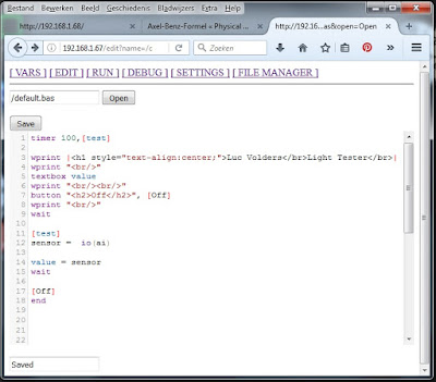
This is going to be a small project which can have many uses in your Android projects. We are going to make your phone speak to you !!

Now why is this of importance. Well simply said this can give an audible feedback to any commands you are going to give to your phone in future IOT projects. And I am going to show you how easy it is to make an Android APP with the fabulous MIT App-Inventor. Mind you this is not a total instruction from scratch. I presume you know the basics of working with App-Inventor and otherwise I advise you to look at the tutorials on the web as App Inventor is really easy to work with.


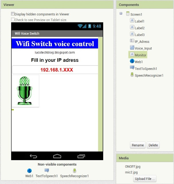
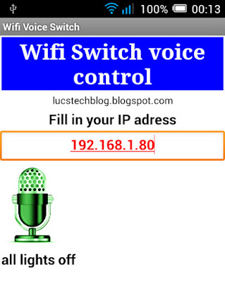
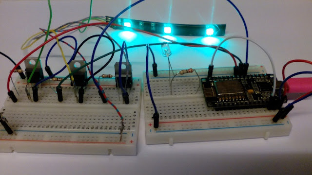
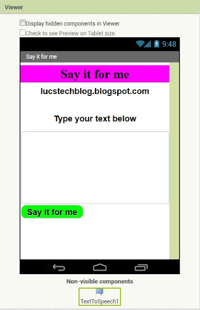
Look at the picture above and most steps below will be easily understandable.

So first start a new project and call it "Say it for me".
Next add some labels that will contain just plain text. I made 3 labels.
First label is the pink one containing the name of the app in a 30 points fontsize, a magenta backgroundcolor and bold black text.
The second label (Label 2) contains the name of my weblog and has a fontsize of 20,
The third and last label (Label 3) gives the instruction  to type your text in the field below it.

Then there is a textbox, obviously called Textbox 1, in which you can type any text you like. I set the fontsize at 14. Just make sure you check the multiline option so you can actually fill in multiple lines of text. If you do not check the multiline option all text will scroll on just one line which will make things inconvenient.

Then the last visible thing on the App's page is a large green button (Button 1) with a rounded shape and a bold font size 20.

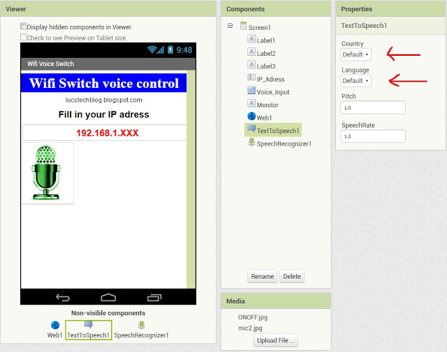
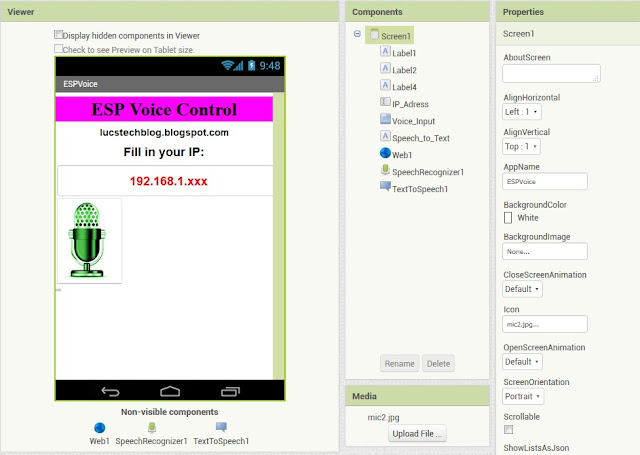
There is one last very important item but that will be working in the background and therefore has no visible part on the screen and that is the TextToSpeech function which you can find on the left part of the screen in the "media" section. Drag this to your workspace and it will be put at the bottom as a non-visible component.


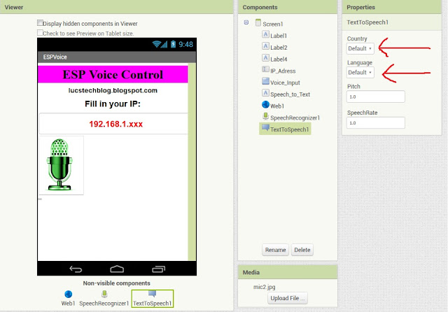
If you click this component you can choose on the right side in the Properties section which language will be spoken and at what pitch and speechrate. The last two are less important as the first. By choosing a different language as the filled-in Default option your phone will pronounce the words in that language. Be aware that by changing the language the speech of for example your navigation system will alter also to the new setting. So most of you will leave this at the default settings.

To finish things off in a professional way I added a nice looking Icon to the screen You can do that by clicking on the black strip in your workspace. App Inventor shows you on the right side of the screen the settings for your App and you can fill in (amongst others) the App-name, screen orientation, title and the icon you want for your app. You can upload any picture from your computer and most formats (JPG, PNG etc) are accepted.

That's it for the layout.

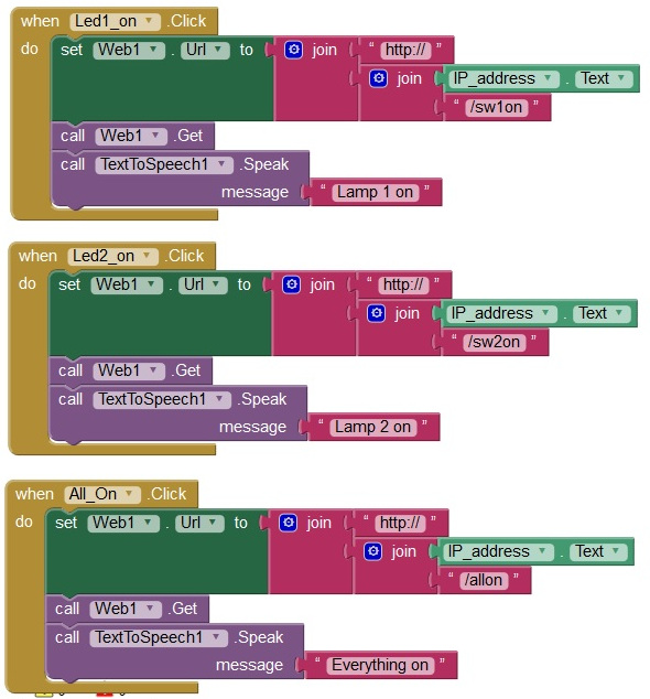
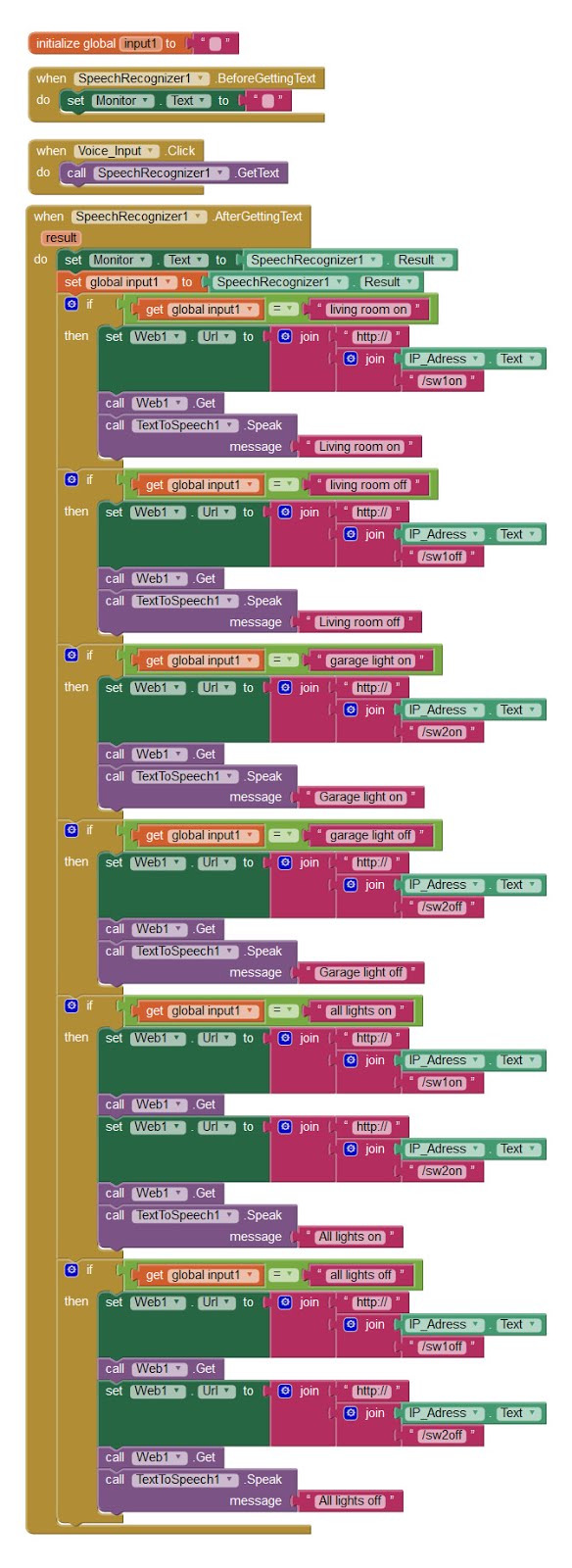
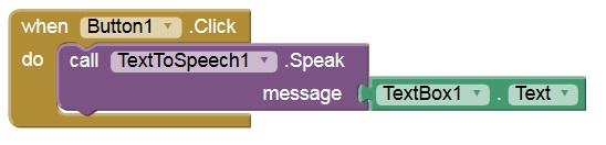
Lets look at the code in blocks.


Well this is all.
When the button is clicked we call TextToSpeech and let the App pronounce the Text in TextBox1

In Real Life

Usage is very simple. You just put any text you like in the textbox by typing it in or by copying it from a webpage, note or whatever and press the green "Say it for me" button. A nice female voice will pronounce whatever you typed.

Now go and get a flush on some people's faces by having your phone speak all kinds of texts like "Yes master I will obey you in every way you want."

And for a more serious note.
App Inventor really makes it easy to make all kinds of app's for your Android Phone, and we are going to use this speech synthesizes in some upcoming apps. So stay tuned.

All that rests is a link to the App and the source file (ending on .aia) which you can alter as you like with your own App-inventor account.

Speak to me sources

Copy the files to your own computer. The file ending in .aia can be loaded in App-Inventor to alter to your own needs. The file ending in .apk can be transferred to your Android-phone. clicking on it will install it and you are ready to go.

Till next time, and make sure to have some fun

Luc Volders

ESP8266 Computer

$
0
0
I really love the ESP8266. It is a real versatile devellopment platform with loads of possibillities and potential. My favorite module is the NodeMCU version with loads of memory, all its I/O ports available a build in power regulator and ready to program over USB or even OTA (Over The Air).

For many purposes, especially in the Internet Of Things world, the I/O ports are needed to control relays, leds, temperature sensors, light sensors etc. etc. etc.

However I am doing some projects for which I just need the processing power and the Wifi. And sometimes I need it to be portable. One of the projects I am working on is a vault for my all my passwords. I do not need any I/O ports for that. Another project I am working on has to do with wardriving. No I/O ports needed for that either.

So what I wanted was a small casing in which I could secure my ESP module and that had a small opening for a USB cable to power it be it from a computer or from a power-bank.


I started by designing a casing and the lid in 123D-design.


Printing was quick and no problems occurred. I had to do a tiny bit of sanding afterwards. But the result was very satisfactory.


My NodeMCU V.09 (I still have a few of them) snuggles nicely in and the USB cable fits exactly.

And then........

As I was surfing the net a nice story came up on from favorite hack(st)er Lady Ada.


Just look at this beauty.


I just had to print one as the Commodore PET was one of my first computers when I was a kid (well I was 18 back then). Pink is an issue. I bougth 8 kilo pink PLA at an unbeatable price (20 euro for the lot), so most things I print have to be pink now..........


And look the ESP nicely fits in.

So now I have two choices. The small package and the retro version.

For those interested in printing one of my cases for themselves I herebye give you the link to my Gitbub page. You can import the STL files in 123D-design to edit them and make them fit for the newer NodeMCU versions.


https://github.com/Lucvolders/ESP8266-case

For those interested in the Lady Ada  version is here the link to her website:

https://learn.adafruit.com/mini-commodore-pet-with-charlieplexed-led-matrix

I am going to scale the PET version up and put an Oled-screen inside and some leds and a buzzer and neopixels and make the I/O ports accessible from the outside so I have a full-blown test ESP available. But that's for another story. So much ideas, so little time.


UPDATE


There it is. I found the time. Inside is a NodeMCU. The blue square is a small 0.96 inch Oled screen attached to D3 and D4. Beneath that there is a strip of 8 neopixels attached to D8.
The keyboard has been substituted by 4 switches that connect 4 i/o (D2, D5, D6 and D7) ports either to the 4 leds or to a header which allows me to attach several other sensors, switches, servo's etc etc etc. A small buzzer attached to D1 is placed into the casing.

If you want to build one for yourself just go to the above mentioned Adafruit website and scale the STL files up 1.5 times. That will be enough.


If you are interested in the story about wardriving, the password vault or my other projects keep coming back frequently.

Till next time
Have fun

Luc Volders

Powering your project

$
0
0
In the beginning of this year I was asked to give a demonstration about using electronics in gardening. For this I made a small setup in which I used an ESP8266 (a Wemos D1 mini version) to test soil humidity. As soon as humidity dropped below a certain value a water pump would irrigate the soil.

As a soil humidity tester I just used two wires attached to the analog input of the ESP8266. And I purchased a nice small pump that is nevertheless capable of pumping 80 liter water within an hour. The ESP's datapin is not powerfull enough to run the motor of the pump so I used a TIP120 as a signal amplifier. In theory everything worked as planned. However in reality not exactly.


I was powering all this from the ESP itself. I used a Wemos D1 mini version. The Wemos D1 can be powered by a USB cable and has both 3.3volts and 5 volts output as you can see on the picture. The 5 volts is on the right side and the 3.3 volts on the left side.

Well actually everything did work however the pump was not pumping constantly but it was stuttering. It took me a while to realise that when the pump started working it influenced the reading from the analog port. And that was due to the fact that the voltage regulators on the Wemos D1 mini where not able to supply enough current.

So what to do.
Well the solution is obvious. I needed to power the pump circuit (pump with TIP120) with a separate power supply.

Now I could make a cut in the USB cable and drain some power seperately to my circuit. However there is an easier solution.


At the local dollar store (called Action in the Netherlands) they sell a wall plug with a double USB outlet.


And on my Chinese suppliers site I had bought a few weeks before a micro USB connector for PCB mounting that easily fits on a breadboard.


As you can see this makes life much easier. The only thing is that you need to use 2 usb cables.


An even easier solution was something I found later on the Chinese suppliers website: a USB splitter cable. That is even easier as you will not need to purchase a special wallplug with a double USB connection. I haven't bought one of these yet but I am surely going to.

Just make sure that your wall plug delivers enough Amps to power your circuit. Mines supply 2.1 amps which is more as sufficient for ESP projects.

Till next time.
Have fun.

Luc Volders

Watch your cables

$
0
0
I was doing a project with a Raspberry Pi 3 when I encountered a strange problem.

I installed the Raspberry OS and wrote my software. next I tested it thoroughly until I was convinced everything worked as I planned. Next step was to move the Raspberry to its working location.


The location I planned for the raspberry had no wall power outlet. So I used a 5 meter long (16 foot) USB cable as a power source. Should be no problem as this cable powered a NodeMCU before.

But then the trouble started.

The Raspberry started as planned and then suddenly resetted. So I detached the power cable and re-attached it to reboot the Raspberry. That worked, however after a few seconds it resetted again.

I was sure I had a decent USB power supply attached: 5 Volts, 2.1 Amps. More as sufficient. And then I got an idea. I relocated the Raspberry and attached the original USB cable (1.8 meter) again. And everything worked as normal. So I replaced the 1.8 meter USB cable with the 5 meter cable and the problems started again: fault located !!!
The cable obviously had to much resistance which reduced the power.

I had used this cable with a NodeMCU before but obviously that draws less power as A Raspberry Pi 3 does.

So if you have power problems with your Raspberry Pi do not automatically suspect the power supply, but check the cables also.

Till next time,
Luc Volders

9 volt power plug salvage

$
0
0
I bought this fantastic piece of equipment. it is a kind of multi-tester. Not like any ordinary multimeter, no a multitester.


Not only does it tests resistors but also capacitors, transistors (PNP and NPN) fet's, diodes etc. It can be found on all the well-known chinese web-shops for just a few dollar. But that is a different story all together. It has only one flaw: it works on 9 volt batteries. The availability of the 9 volt batteries is not such a problem as well as the cost and lifespan.

After some examining of the multiteter I realised it was powered by a 7805 5 volt regulator. Powering it with a slightly divergent power supply would therefore not lead to problems. And I had such a power supply at hand. It is a 9 volt power supply.

However my multimeter showed it supplies 11 volts when unencumbered. No sweat: the 7805 should be able to handle that.

I could cut the 9 volt plug and solder the wires direct to the multitester. But I wanted a more flexible solution that would permit me to use the power supply also for different purposes. Therefore I needed a 9 volt contra plug. And that was easily found.


There is a 9 volt plug on top of the battery. Now I have seen instructions on how to decap the battery and salvage the plug. I have never done such a thing myself and looking at pictures on the internet is not the same as doing it yourself.


I examined the battery slosely and saw that there was a juncture. So I started tweaking at the juncture and to my surprise it was the start of a label that was glued to the casing. So the label came off easily and beneath it was a plasic casing. You might not be so lucky as I know that many cases are made of metal so cutting them up might be more tedious.


Next step was to carefully saw the bottom off. And when I made a big enough cut I ripped it with some pliers.


Inside was a pack of 3 batteries soldered together with some long flat leeds.


I removed the batteries and the remains of the casing until just the plug was lying in front of me.


Then I cut the long flat leads off.


Next step was examining the battery and looking which pole was corresponding with VCC and which corresponded with GND. The small round pole is the VCC side and the large split pole is GND.


The only remaining step was then to solder the wires of the power supply to the poles and all was done.


A final test with my multimeter showed that everything was fine and indeed when I plugged it to my multitester it worked as expected.


This is an excellent way to save on batteries.
Just make sure that anything you plug this power supply into has to be capable of handling the supplied voltage which is in my case about 11 volts.

Till next time.
Have fun.

Luc Volders

Oh no, not another wifi thermometer.

$
0
0

I know. It is stupid. And at first I was not even sure why I was building it. As the internet is paved with ESP-Weatherstations and thermometers. And why on earth is the weather so interesting. Just look outside and you know what it is like. And then a reason came up. For testing all kind off IOT cloud services I needed a device that would constantly provided some data and what is easier as a thermometer to provide data.  However I had some demands.

Price.
It should be really low cost. and it is !!! I used an ESP-01 (1.57 euro) a Dallas 18b20 temperature sensor (0.98 euro) a LM317 voltage regulator (0.08 euro) , some resistors (about 0.05 euro) and a USB cable (about 1 euro). That sums up to 3,68 euro. Add some stripboard and wire and there is your complete thermometer for about 4 euro.
Naturally I printed the casing myself.

Simple.
This project should not take more as a few hours to build. I made a prototype on a breadboard and when that worked I transferred it to some stripboard. Programming was done in the unmatched easy ESP-Basic language.

Before we start.
Before we really start with this project I want to point out some basic knowledge articles I wrote that helps you understand how all fits together.
First read about the LM317T voltage regulator which allows you to provide your project with any voltage you might need. Read that story by clicking here.
 

And please read the introduction article to ESP-Basic which makes developping ESP8266 projects a piece of cake. The introduction article runs you through flashing ESP-Basic and using the web-based editor to writing your first programs.

Let's go.

Powering the project.

The ESP-01 works at a 3.3Volt power level. And the Dallas Temperature sensor fortunately also does so. I am going to power this project from a USB power source (be it a computer, mains adapter or powerbank). So the USB power, which is 5 volt has to be reduced to 3.3 volts.

As stated above I am doing this by the use of a LM317T voltage regulator. 5 Volt is supplied and reduced to 3.3 Volts.


As you can see from the schematics above we will need a resistor of 1.2K and a resistor of 2K to achieve this. Like  I said above: for more information about this read the article about the LM317T.


The breadboard shows you the setup.

The ESP side

For flashing ESP-Basic and programming I used my ESP-01 programming board which I described in detail in the story you will find by clicking here.


As you know the Dallas 18B20 needs a pull-up resistor of 4K7 to function. So I attached my programming board to a small breadboard on which I placed the resistor and connected the Dallas temperature sensor.

At first to make life easy I soldered some paperclip wire to the Dallas 18b20 wires so I could easily fit them on the breadboard. The paperclip trick is one I use often. For those of you not familiar with itclick here to read the story. Later on I replaced them with dupont wires cut in half and soldered to the Dallas 18B20 wires.


 So when this all functioned I completed the setup on the breadboard.


And when all functioned as it should I put it on two left-over pieces off stripboard.

The program.

 Timer 5000, [start]  

wprint "<!DOCTYPE html>"
wprint "<html> <body>"
wprint |<body style="background-color:greenyellow;">|
wprint |<H1><span style="color: red;">|
wprint " A thermometer"
wprint "</H1>"
wprint "</span>"
wprint |<H2><span style="color: blue;">|
wprint "Temperature is now "
textbox test

a = "background-color:greenyellow;"
a = a & "display:block;width:80px;"
a = a & "border-style: hidden;"
a = a & "font-size: 22px;"
a = a & "font-weight: bold;"
a = a & "color: fuchsia ;"
cssid htmlid(), a
wprint "</span>"
wprint "</H2>"
Wait

[start]
test = temp(0)
test = ((int(test*10))/10)
wait


The program may look complicated but regard it closely and you will see that in reality it is not. There are some neat tricks in it though.

Let's simplify it first.

There are just 3 lines that actually are the real program core:

test = temp(0)
test = ((int(test*10))/10)


The first line reads the Dallas 18B20 temperature sensor. And the second line rounds it to 1 decimal.

textbox test

This line actually puts the temperature on the screen. Those are the three core lines. All that follows is just pimping it up.

Timer 5000, [start]

To make the program check the temperature each 5 minutes we use the Timer command as you can see in the line above.

wprint |<body style="background-color:greenyellow;">

This sets the background of the web-page in the color "greenyellow"

a = "background-color:greenyellow;"
a = a & "display:block;width:80px;"
a = a & "border-style: hidden;"
a = a & "font-size: 22px;"
a = a & "font-weight: bold;"
a = a & "color: fuchsia ;"
cssid htmlid(), a


That is an important block of CSS code.
What it actually does is to hide the contour of the textblock, give the textblock the same background as the webpage has and gives the text in the textblock a contrasting colour.
All this together hides the textblock from the screen and makes it look as if the text is printed direct on the webpage. And that is a really nice trick.


And here is the end-result.

Casing


The casing is identical to the casing I made for the PIR alarm (click here to look at that project).


 The difference is that the lid has no opening for the PIR. It is just massive


As you can see the case is far to large for such a small stripboard and therefore has one advantage: you can also power this project  with AA batteries.

That's it.

All that rests is to give you the links to the STL files so you can replicate or adapt this to your own needs.

https://github.com/Lucvolders/Wifi-Thermometer

Till next time, have fun

Luc Volders

Thingspeak

$
0
0
This weblog has described many projects that connect all kinds of sensors and switches to your network. We had an ESP Controlled ledstrip, a rain sensor, an ESP controlled relay, a thermometer and many more.

All these projects have something in common and that is that they attach an ESP to a web-page which can be controlled from your computer or phone. This works great when you are inside the environment of your wifi home network.

However not all projects are intended to be used from within your home or office. Sometimes you need to control things from another location (your office, on a holliday, visiting friends etc). That implies that you need to open a port on your home router so the information can get out your local environment. This is called port-forwarding.
So if you have multiple sensors and switches attached to multiple ESP's in your house you will need to open many ports on your router and that could (mind you I do not say "will") bring a safety issue. Opening ports on a router may open a port to a hacker, and that is something we certainly do not want to happen.

There are multiple solutions to this. One involves an intercommunication system amongst your ESP's. Meaning that all your ESP's talk to eachother and just you have one central system (being an ESP or a Raspberry) talking to the outside world. That is not the solution I am going to talk about here.

The solution I am going to discuss is using an external IOT platform.

What is an external IOT platform.

Basically it is a computer system run by a company that has an internet connection and allows you to send data to. This data will be put on an open or private webpage which you can access from any part in the world.
The advantage is that any device in your network only has to send data to this computer just like your home computer sends and receives data to and from the internet.

No need to open ports in your router, and often they offer a fancy interface that is easy to use. So there is not a lot of programming hassle.

Thingspeak


In this example I am going to demonstrate how you can put the information from the ESP-Thermometer on to the world-wide-web and read the temperature in your home from any place in the world. I am using the Thingspeak service for this as it has a very easy interface which can be used easily from ESP-Basic or the Arduino environment.

So the first thing you will have to do is to visit the Thingspeak website: https://thingspeak.com/

If you not have an account already (if you have you would not be reading this) Sign Up for an account. You will be asked an e-mail adress, a user ID (which you can define yourself) and a password. Remember both the user ID and the password. You wil be needing them both in the future.


After successfully signing up you will start at the channels page. At this moment you will not have any channels so choose to make a new one. You will be taken to a new page where you can fill in the details of this channel.


Above you can see that I filled in the first details for this channel. Give each channel an identifying name and fill in a fitting description. We will only have one field in this channel being the temperature. If you would have multiple sensors attached to your ESP you could for example have a second filed that represents a door movement. That way you could relate between an opening door and the temperature.


Scrolling down there are more fields which you can fill in which are not necessary exept one important one. That's the field you have to check to make your channel private or public.
Public channels can be accessed by anyone without even having to login. For now make it public.

Now press the Save button.


You will be represented with another screen that shows you the most important part: a chart with your workroom temperature. Off course there will be no information filled in yet.

As you can see there are 3 buttons. Two of them are important at first. The "More Information" button brings you to your own webpage. The "Data Export" button makes it possible to save all the data in a JSON, XML or CSV file on your computer for off-line analysing.


The most important TAB is the API Keys tab.
Here you will find your personal key for writing information to Thingspeak or reading information out of a channel.

For now we will only be looking to writing information to a channel. We will need the Write API key for that. So leave this screen open so you can easily copy the API key later on in your program.

Writing thermometer values to Thingspeak.


In the article "Oh no not another thermometer" I build a.....thermometer that displays the temperature on a webpage using an ESP and a Dallas 18b20 sensor. I programmed it in ESP-Basic and it has been functioning for many weeks in a row flawlessly. But it was only accessible from within my own home-network. Now we are going to bring it in the open.

Open a webpage and access the thermometer. If you do not know how to find it look at this article which gives you the basic information about ESP-Basic.


tel=0
Timer5000,[start]

wprint"<!DOCTYPE html>"
wprint"<html> <body>"
wprint|<bodystyle="background-color:greenyellow;">|
wprint|<H1><spanstyle="color: red;">|
wprint" A thermometer"
wprint"</H1>"
wprint"</span>"
wprint|<H2><span

style="color: blue;">|
wprint"Temperature is now "
textboxtest

a="background-color:greenyellow;"
a=a&"display:block;width:80px;"
a=a&"border-style: hidden;"
a=a&"font-size: 22px;"
a=a&"font-weight: bold;"
a=a&"color: fuchsia ;"
cssidhtmlid(),a
wprint"</span>"
wprint"</H2>"
Wait

[start]
test=temp(0)
test=((int(test*10))/10)
tel=tel+1
iftel=360then
tel=0
gosub[thing]
endif
wait

[thing]
sendthing=str(test)
SENDTS("MY-API-KEY","1",sendthing)


return

Now open the Edit page and look how I altered the Basic Program.

What I wanted to do is to have the thermometer send it's information each half hour to the thingspeak channel. Therefore I altered three things in the program.

tel=0

I inserted this line to the top of the program to initiate a new variable.

[start]
test = temp(0)
test = ((int(test*10))/10)
tel=tel+1
if tel = 360 then
  tel = 0
  gosub [thing]
endif
wait

I altered this routine so that each time the routine is called (every 5 seconds which is set by the TIMER 5000 command) 1 is added to tell. And if tell has reached the value 360 (which is in time 5 seconds * 360 = 30 minutes) the routine [thing] is called.

[thing]
sendthing = str(test)
SENDTS("MY-API-KEY", "1", sendthing)
return

So eacht time (every 30 minutes) when this routine is called the string variable sendthing is filled with the actual temperature (test). And then SENDTS("MY-API-KEY", "1", sendthing) sends the information to field "1" in my Thingspeak channel. If you have more fields you obviously alter the "1" in the field you want to write to.


In the mean time the information on the local webpage will still be updated every 5 seconds.

You will have to substitute MY-API-KEY with your own key which you can find at the API-KEY tab in your channel. Make sure you use the "Write API Key" and not the read one which is used to read information from the page, nor for putting info on it.

That's all !!

Run the Basic program and just wait.


Here you can see the temperature in my room over a period of one and a half day.

More information needed

Thingspeak is free as in free beer as long as you do not exceed 8200 messages a day or 3.000.000 (yes 3 million) messages a year. You can update the info every 15 seconds.

If you have multiple sensors connected to an ESP you can add more fields in a channel or even open more channels depending on how you want to present the data. By opening multiple channels you have to use multiple API-Keys, one for each sensor.
If you are using multiple ESP's you can have them writing to the same channel, so you can have one graph with temperatures of several chambers in your house. Or you can open multiple channels, each ESP it's own.

Just decide what is most convenient for your projects.

However keep the limits in mind. And make sure the writing of data on each filed or channel overlaps as you can update only once every 15 seconds.

Minimalistic setup.

As ESP-Basic is really awesome for rapid devellopment I will give you a minimalistic setup here.

Timer 1800000, [start]
wait

[thing]
sendthing = str(temp(0))
SENDTS("MY-API-KEY", "1", sendthing)
return

These 7 lines is all it takes to send the information to my Thingspeak channel. The setback is that there is no fancy local webpage I can access on my phone or tablet to have a look at the temperature. You can only get the information through Thingspeak.

Even better.

To access your information you can log in from any place in the world to the thingspeak. But it even gets better. You even do not need to login for getting at your info.


Just go the Thingspeak website.

And in the top tabs choose "Channels"You will be presented by a similar page as shown here.


Now fill in your user ID on the right side of the screen and it will give you your channels


Clicking on the name of the channel in the blue banner will direct you to the information.


Remember this part of the setup page. You filled in "Make Public"
Setting a channel as public means that you even do not have to log in to access the information.

Be carefull

As said above a channell's information is accessible for anyone if it is set to public. That really means that anyone in the world can have access to the information. So be carefull.
Do not use your real name in Public information. Give no clues about who you are, what your location is etc etc etc.

Suppose you have a public channel that displays the information in your house. Or the water usage, or the time the lights are on etc etc etc. If the information is public this is valuable info for any burglar or thieves. Read here about this privacy issue: http://lucstechblog.blogspot.nl/2017/02/burglars-invited.html

In future stories I will show you how to send info to Thingspeak with the Arduino IDE and I will show you how to get information from the Thingspeak channel to perform actions on.


What more IOT platforms are avalable ?
 

Actually there are quite a few IOT platforms available. Some of them are equally easy to use like Thingspeak. Examples are Dweet and IotTweet which I am going to discuss in previous stories.

Others like Blynk and Cayenne IOThave many advantages and possibillities. However they require you to install libraries in your ESP. This will work while programming in the Arduino IDE but not (yet) in Basic. Programming is more difficult. And this article is aimed at fast results. Besides that Blynk is only free to a certain amount of channels.

Nevertheless it is something I will be checking into in future stories.

Till next time
Have fun

Luc Volders

Analog Pull-Down resistor

$
0
0
We all realise the importance of the pull-up resistor on a digital input pin.
Without a pull-up resistor the initial state of a digital pin is floating and we never will get an accurate reading.

However I never realised how important the pull-up resistor is in an analog circuit. And now I understand it fully I can give you an excellent simple example that demonstrates how valuable such a pull-up resistor is.

Normally an Arduino or an ESP-8266 can read it's analog input and gives it a value between 0 and 1023.
Lets see what happens when we do not use a pull-down resistor and attach an LDR directly to the analog input. In this example I am using an ESP-8266.


Look at the breadboard. The LDR is on one side connected to 3.3 Volts and the other side directly to the analog input of the NodeMCU.


timer100,[test]

wprint|<h1style="text-align:center;">LucVolders</br>LightTester</br>|
wprint"<br/>"
textboxvalue
wprint"<br/><br/>"
button"<h2>Off</h2>",[Off]
wprint"<br/>"
wait

[test]
sensor=io(ai)

value=sensor
wait

[Off]
end


So I wrote a small BASIC program that just reads the analog input port and displays it on a web-page.


When fully exposed to the light the analog reading was 958. When fully covered the reading was 984. Well it kind of works however there is not a lot margin for error. So this is not very usable.

I started searching the net for an LDR setup and indeed there were many examples. They all used a 10K pull-down resistor.


I altered my breadboard setup and attached a 10K pull-down resistor. And indeed it worked.


The value I measured when the LDR was in full light was 527 and when covered with my finger I measured 933. Now this is a much wider range so there is a wider range measurable when the LDR is just partly covered. However it was still not using the full range.


AXEL BENZ FORMULA


Then I found the  Axel-Benz formula.
The Axel-Benz formula is honorably named after one of the first teachers of Physical Computing at the FH Postdam.

How does this formula actually works out.

The formula R-ref = SQR (R-min * R-max) tells us that the value of the of the pull-down resistor should be the Square Root of the (minimal resistance * maximum resistance).

Lets start with measuring the minimal and maximum resistance. We'll do that using our trusted multimeter.


As you can see the value I measured when the LDR was exposed to full light was 420 Ohm. When I covered the LDR with my finger I measured a value of 18.500 Ohm. Now I would have expected a much higher resistance when the LDR was covered so there might be some light leaking around my finger.

Now let us use these figures in the formula.
The formula is: R-REF = SQR (MINIMAL * MAXIMAL)

Lets substitute our figures into the formula:
R-REF = SQR (420 * 18500)
R-REF = SQR (7770000)
R-REF = 2787

This gives us a resistor vaule of 2787 OHM. The nearest by existing value that we can use is a resistor of 2.7K


Therefore I substituted the 10K resistor on the breadboard to a 2.7K version.


And the result is fantastic. The measured values now vary between 257 and 847. This a much broader range in which we can measure more accurately the amount of light that is exposed onto the LDR.

Arduino test


intsensorPin=A0;
intsensorValue=0;

voidsetup()
{
Serial.begin(9600);
}

voidloop()
{
sensorValue=analogRead(sensorPin);
delay(sensorValue);
Serial.println(sensorValue);
}

The above experiment is done with an ESP-8266. But how would it work on an Arduino. Well here is the code I used for measuring the Analog port.


I measured the value on port A0.


And here you can see that the values I achieved are almost the same as the ESP gave.

Is everybody Stark Raving Mad then ???

Why on earth is everyone using a 10K resistor then. Has the world gone mad. Well actually yes it has. Just look around you. however not concerning this  particular case.

When you have a full bright light the LDR will have a value of about 0 to 10 OHM. In absolute adrkness it will be around 10000000 (10 meg). Now if we use these values in the formula it will work out as follows:

R-REF = SQR (10 * 10000000)
R-REF = SQR (100000000)
R-REF = 10000

And there we have the 10K value.

However as we saw in the beginning of this story this value did not work out well in this particular case.

So the lesson learned is to always calculate the best value for the project you have at hand.

Till next time
Have fun

Luc Volders

Lightmouse

$
0
0
While surfing over the internet I stumbled upon the Leap Motion Controller and I was flabbergasted. It was something that that really amazed me. Controlling your computer with your hands instead of a mouse. I wanted one.

Then I started thinking. Wouldn't it be possible to make something like this by myself. Well not actually tracking the movement of your fingers. That would be to complicated. But tracking the movement of a hand should be possible.

The general idea was that when your hand moves over a surface the place where the hand is, is in the shade and the rest would be in the light. And that is something you can easily measure by using LDR's (Light Dependend Resistors). So I made a simple setup.


I used two small breadboards next to eachother. This makes it possible to put the LDR's on the breadboard at a certain distance. I attached the LDR's to the analog ports of the Arduino Pro Micro.

Mind you: for this project you really need an Arduino Pro Micro as this has a real USB interface and not a USB-serial interface. We will be needing the USB interface for simulating a mouse.

The LDR's have a pull down resistor for more accurate measuring. To calculate which value the pull-down resistor needs in your particular case use the formula described in this article.
If you do not use the right pull-down resistors the setup will not function  as intended and react poorly at your movements.
In my setup I am using 10K resistors because my setup is intended to work in full light. However if you are using this in more ambient circumstances make sure you alter the values of the resistors using the described formula in the formentioned article.

The first tests were done by just reading the values the LDR's would give when I moved my hand above it. And the results were very satisfying.

Now I had to find the right formula for making something usefull out of this.

Let us look at the following simplified setup.


The square represents the total setup and the black dots represent the LDR's.

If I want to go left my hand has to cover LDR A and C.
For going right it has to cover B and D
Up means covering A and B
Going down can be achieved by covering C and D

By covering the individual leds I indicate that I want to go diagonal.

This can be easily represented in a formula.
Think about this.
If I cover LDR A and C they will get less light as LDR B and D.

X direction =  (A+C) - (B +D)

If the outcome is negative I am moving left. If the outcome is positive I am moving right. Remember that the LDR's give a higher value where there is more light.

Y direction = (A+B) - (C+D)

Same drill as the X direction.

The individual leds are even easier.

If the Value of LDR A drops then I am covering the LDR and want to move UP-LEFT.

And this is really all that is to it.

The only thing I need to test is wether I am actually moving my hand above the setup.
That can easily be done by the following test:

  x = ((A+C) -(B+D));
  y = ((A+B )- (C+D));
  axy = (abs(abs(x)-abs(y)));
 
  if ((abs(x)>25) && (abs(y)>25))

Look at this formula. It just tests if the difference between X and Y is bigger as 25 and that indicates that something is going on above the LDR's. I have substituted the formula in my program by using the variables s1 to s3 which represent the analog lines A0 to A3.

Now we only have to tell the Arduino Pro Micro that it has to act as a mouse by the following command:

void setup()
{
  Mouse.begin();
}

And here we get at a more difficult part of the program. Look at the following lines:

  if ((x<0) && ((abs(x))>(abs(y))) && (y>0) && (axy>100))
    {
      //going left
      Mouse.move(-10, 0, 0);
    }


Let's examine it in detail.

 if ((x<0) && ((abs(x))>(abs(y))) && (y>0)

The first part just tests if  X = smaller as 0. If that is true then this means you want to move left.
As a safety measure I also test if the X value is really bigger as the Y value. That indicates that there is indeed less light on the X LDR's.

&& (axy>100))

This last part tests wether there is a significant difference between the X and Y values. That is to make sure it is my hand moving above the LDR's and not just some shade of a cloud passing by.

Just one last thing to do:

Mouse.move(-10, 0, 0);

And that is why you need to use the Arduino Pro Micro.
This command actually moves the mousepointer of your PC (or Raspberry) to the left by 10 pixels. The 0 following the -10 makes sure that the mouse stays on the same line (Y-coordinate( and just the X moves. The second 0 indicates that the scroll wheel of the mouse should do nothing.

So here is the full listing:


/*Light Mouse
Luc Volders

Decides on which way the mouse will go by checking
which LDR's get light on and which do not

using 4 LDR's put in a square form
top: A1, A3
bottom: A0, A2
*/


ints1,s2,s3,s4,x,y,axy;


voidsetup()
{
Mouse.begin();
}

voidloop(){

s1=analogRead(A0);
s2=analogRead(A1);
s3=analogRead(A2);
s4=analogRead(A3);

x=((s3+s4)-(s1+s2));
y=((s1+s3)-(s4+s2));
axy=(abs(abs(x)-abs(y)));

if((abs(x)>25)&&(abs(y)>25))// test for action
{
if((x<0)&&((abs(x))>(abs(y)))&&(y>0)&&(axy>100))
{
//going left
Mouse.move(-10,0,0);
}
if(((x>0)&&(y>0))&&(axy>100))
{
//going right
Mouse.move(10,0,0);
}
if(x<0&&y<0&&axy>100)
{
//going up
Mouse.move(0,-10,0);
}
if(x<0&&(abs(x)<abs(y))&&y>0&&axy>100)
{
//going down
Mouse.move(0,10,0);
}
// -------------------------------------------------------
// schuin
// -------------------------------------------------------
if(((x<0)&&(y<0))&&(axy<100))
{
// moving left-up
Mouse.move(-10,-10,0);
}
if(((x>0)&&(y<0))&&(axy<100))
{
//moving right-up
Mouse.move(10,-10,0);
}
if(((x<0)&&(y>0))&&(axy<100))
{
//moving left-down
Mouse.move(-10,10,0);
}
if(((x>0)&&(y>0))&&(axy<100))
{
//moving right-down
Mouse.move(10,10,0);
}
}

delay(50);
}


After I was sure everything worked fine on the breadboard setup I made an experimental setup using a cardboard.


And after thorough testing I sat behind my computer and designed a casing. This was done in Tinkercad. This design proves that Tinkercad is quite capable.


And this is how it looks in real life.


And man does it work !!!!


I am sorry the video is of such a bad quality but it is the best I could do in my crammed man/cave. I had to make the video using one hand and using the other hand to operate the device.

It also works on my Raspberry Pi and using a USB/OTG adapter it also works on an Android device. I tried it on my Phone and on a tablet with great results.

A lot of possibilities come to my mind for this device. Using it as a joystick for games is obvious. How about adapting the hardware and making a remote for a model boat or car. Gesture controlling a Power-point presentation is another option. Use your imagination.

You can as always find all files on my Github repositry.
https://github.com/Lucvolders/Light-Mouse

So try this for yourselves and have fun.
Till next time

Luc Volders

All stories organised

$
0
0
As this blog grows it becomes more and more difficult to find stories that might interest you.

So I made an index.
You can find it on the top-right side of this page right below the banner under the chapter pages. you can also click (or save) this link:

http://lucstechblog.blogspot.nl/p/index-of-my-stories.html

The index is divided in chapters that represent the point of intrest.
Under each chapter you will find the related stories and a short description.

Look at the sample below:

IOT (Internet of Things)

Back to Basic - introduction to ESP-Basic
Burglars invited- Be carefull what you publisch on public sites
Cheapskate - test wether your fridge light is on or off
ESP Controlled ledstrip- Control a single color ledstrip from a webpage
Google Home and the ESP8266 - Turn on your devices with your voice
IFTTT part 3 Alert over IFTTT - Tweet an alarm when your PIR has noticed motion
IFTTT part 4 - Send a notification to my phone
Rain Sensor- Get an alert on a webpage when it rains
Relay Server  - Control your lights over the internet AND manual


As you can see the point of intrest in this part is IOT and there are at the moment of this writing 9 stories related to IOT alphabetically arranged.

From now the index will be updated each time a new story is published and I will put a pointer to the index on each new story that is published.

Hope you find this usefull.

Luc

Wifi Relay

$
0
0
I have shown you how to control leds and relays over wifi before on this blog. The first time was in May 2016 when I showed you how to control a ledstrip with an ESP8266. You can re-read that story by clicking here.

The second story was about a relay-server that could be accessed over the internet but as a bonus also has manual control. Something I have not seen before and still have not seen in other stories (however the internet is a big place so I can be mistaking). You can re-read that story by clicking here.

These projects and most projects you can find on the internet have one thing in common and that is that they all work using a web-page to send commands to the ledstrips, relays etc.

There might be moments that you want to control things over wifi but not use a webpage for this. An example would be that you need the project being accessed from the internet or your local network, but not seen by everybody or controlled by everybody. I can imagine that you do not want your kids/visitors to control the lights or electronics in your mancave.

Therefore we are going to control an ESP8266 in a totally different way. We are going to make our own Android APP in Mit's App Inventor and write a special program for the ESP8266 that listens to the APP. There is no web-page, so the ESP8266 can only be controlled from the APP and even better: only if you know the exact commands to control it.
To be specific: the app will have buttons to put leds on and off and give an audible feedback in the form of spoken words like I demonstrated in the project that can be found by clicking on this link: http://lucstechblog.blogspot.nl/2017/10/phone-speak-to-me.html

Don't worry. Writing your own APP with App Inventor is very easy and what is more you will get all source code and even the Android APK file here so you can use it right away or alter things to your own needs.

Let's make the APP

This is not going to be a tutorial on how to use App Inventor. I urge you to play around with this program and definitely have a look at all the provided examples and tutorials. Also have a look at all the resources that can be found on the internet about App Inventor. But basically the program is so easy to use that you will be devellopping your own App's in no-time.

The Designer screen

Start with downloading the Wifirelay.aia source code to your computer. Then point your browser to http://appinventor.mit.edu/explore/
On the right side of the screen click on the orange square that says "Create Apps"
Now you can log in with your Google credentials. If you do not have a Google account make sure you get one first.
In the projects menu on the top of your screen choose -- import project(.aia) from my computer.


When done your screen will look the same as above.

On the right side of the screen you will find a column with all the components that are used in your App. Clicking a component will highlight it on the example screen and in the last column on the right side of the screen you will be able to alter the settings for that component.

As you can see there are a few labels that do nothing more as putting text on your screen. Then there is a textbox that allows you when running the App to fill in the IP adress of the ESP8266 that is going to be connected.
Next there is a tablearrangement which makes it possible to put components in rows and columns on the screen.
The tablearrangement contains labels with the name of the led and buttons for setting each led on or off.
The last two components are the Web1 and TextToSpeech1 component. They are very important and working in the back-ground. The Web component takes care of the communiaction between the ESP8266 and the App. The TextToSpeech1 component is going to be used to have the App speak out loud which function it has completed.


There is one thing I really want to Emphasize.
Look at the TextToSpeech1 component carefully. If you leave it at its default values the App will speak out any text in the language you have set as your default language in your phone. If that is English all is well. However my phone is set default to Dutch and therfore the text that will be spoken will sound very awkward. So if English is not the default language on your phone you can change the setting for the TextToSpeech1 component to English or alter the text in the program so it will speak your language.

When all is set switch on the right (top) side of the screen to the blocks section where the actual program will be written.

The Blocks


As you can see the program is divided in 6 blocks. Each block starts a function when one of the buttons on the screen of the phone is pressed. There are six buttons (Led 1 ON, Led 1 OFF, Led 2 ON, Led 2 OFF, ALL ON and ALL OFF) and as you can see each button has its own block of code.


Let's look at one of the blocks in detail.

This is the part of the program that will set Led 1 ON.
This block is executed when the button Led1_on is clicked.
If the button is clicked a web-url will be generated that consist of the IP adres which is found in the text-block IP_adress followed by "/sw1on".
With this information the Web1 function is called and when finished the message "Lamp 1 on" will be heard on your phone as an audible check.

That's all.
All blocks are similar exept for the command that is send through the web and the audible feedback.
Make sure that you alter the words that will be spoken in your own language or set the TextToSpeech1 component to English like discussed above. You can alter the "/sw1on" etc commands in the program, but then make sure that you also alter them in the C program for the ESP8266 that follows in the next steps.


The picture above shows you how the actual screen will look on your Android phone or tablet.

Expanding the APP

As you will have guessed by now it is very easy to expand this App for many more leds/relays. Use the designer screen to add more buttons and then switch back to the blocks screen. First click on a block and then choose Duplicate Block by clicking the right mouse button. Alter the name in the - when - section to the name of the new button. Do not forget that you will have to duplicate both the ON and OFF block and make sure you alter the "/sw1on" and "/sw1off" in the number you are going to add and alter also the speech component.

If you have altered the blocks then let Mit's App Inventor build a new APK for you. If you have not altered anything you can install the provided APK at the bottom of this entry.

The ESP8266 program.

Now the App is ready we'll have a look at the ESP side of this project.

This is written in C++ (generally called Arduino code) and edited and uploaded with the Arduino IDE. So I presume that you have installed the ESP8266 prerequisites in the Arduino IDE. If not do so now. The internet is full of tutorials for this so that should be no problem.

Let's have a look at the program.


 /* 

=================================================
* Controlling NodeMCU through an Android APP
*
* Devices
* ==> Relay1 represented by led 1
* ==> Relay2 represented by led 2
*
* Groups
* ==> All Devices ON/OFF
*
* Program by Luc Volders
* http://lucstechblog.blogspot.nl/
*=================================================*/
#include <ESP8266WiFi.h>
WiFiClient client;
WiFiServer server(80);
const char* ssid = "XXXXXXXXXX";
const char* password = "YYYYYYYYYY";
String command =""; // Command received from Android device
// Set led/relay Pins
int switch1 = 13;
int switch2 = 15;
void setup()
{
Serial.begin(115200);
pinMode(switch1, OUTPUT);
pinMode(switch2, OUTPUT);
digitalWrite(switch1,LOW);
digitalWrite(switch2,LOW);
connectWiFi();
server.begin();
}
void loop()
{
client = server.available();
if (!client) return;
command = checkClient ();
if (command == "sw1on") digitalWrite(switch1,HIGH);
else if (command == "sw1off") digitalWrite(switch1,LOW);
else if (command == "sw2on") digitalWrite(switch2,HIGH);
else if (command == "sw2off") digitalWrite(switch2,LOW);
else if (command == "allon")
{
digitalWrite(switch1,HIGH);
digitalWrite(switch2,HIGH);
}
else if (command == "alloff")
{
digitalWrite(switch1,LOW);
digitalWrite(switch2,LOW);
}
sendBackEcho(command); // send command echo back to android device
command = "";
}
/* connecting WiFi */
void connectWiFi()
{
Serial.println("Connecting to WIFI");
WiFi.begin(ssid, password);
while ((!(WiFi.status() == WL_CONNECTED)))
{
delay(300);
Serial.print("..");
}
Serial.println("");
Serial.println("WiFi connection established");
Serial.println("IP number is : ");
Serial.print((WiFi.localIP()));
}
/* check command received from Android Device */
String checkClient (void)
{
while(!client.available()) delay(1);
String request = client.readStringUntil('\r');
request.remove(0, 5);
request.remove(request.length()-9,9);
return request;
}
/* send command echo back to android device */
void sendBackEcho(String echo)
{
client.println("HTTP/1.1 200 OK");
client.println("Content-Type: text/html");
client.println("");
client.println("<!DOCTYPE HTML>");
client.println("<html>");
client.println(echo);
client.println("</html>");
client.stop();
delay(1);
}

First replace the XXXXXX and YYYYY in the program with the name and password for your router.

As you can see I use pin 13 and 15 as the pins where the leds will be attached (which equals D7 and D8 on the NodeMCU). You can alter them for your own needs or leave them as they are. If you added more switches in the App you need to assign more pins for leds.

Halfway down the program you cann see the checks for the commands sw1on and sw1off etc.
If you have altered the names for the commands in your App you will need to alter them here to. And if you have added more buttons in the App you will need to add more commands here.

The program has some serial communication which can be helpfull when debugging it. If all works flawlessly you can comment the serial communication out or delete the relevant lines.

The rest of the program takes care of receiving the commands from the App.

Upload the program to your ESP8266 and you're set to go.

The Hardware


The hardware setup is straightforward as the above breadboard setup shows you. I have used a red led and a blue led for demonstration purposes.The delimiting resistor is 220 ohm, and attached to GPIO13 and GPIO15.


The schematics are pretty straightforward too and the photo shows you my setup on a breadboard.

You can change the leds for dedicated relays like I used in the relay commander project that you can find by clicking here.

Or use a general relay controlled by a BC547 as in the project you can find by clicking here.


Where is it

In the App you need to fill in the IP adress of the ESP8266. There are 2 ways to find that IP adress.

You can use the Arduino IDE and open the serial monitor at 115200 baud. The program will show you the IP adress.

The second way is to open the web-page of your router like I did in the following picture.


The four icons on the bottom of the screen are my wired stations: a raspberry network server attached to my Epson printer, My Computer called Nescio, my Domoticz home automation system and a Buffalo Nas.
The three top Icons represent my wireless stations. The first one is an ESP that is a permanent Thermometer that serves a web-page and send info to Thingspeak (all written in ESP-Basic), my Andoid Phone and an unknown station. That last one is the interesting one.


These are the details for the unknown wireless device and there we have the IP number we are looking for.

Real life demo

Fill in the found IP-number in the App and start pushing the buttons.


The video shows you how the app functions although that is very obvious. You can clearly hear how the speech component works.

Remember the great dictator series on this blog ???
Well then you will know what the next step will be. Commanding your lights with your voice.

Rests me only to give you the links to the source code and the APK file for direct install:

https://github.com/Lucvolders/Wifi-relay

Till then.
Have fun


Luc Volders

Wifi Voice Commander

$
0
0
For an index to all of my stories click here.

In the previous entry in this series I demonstrated how to make an App in Mit's App Inventor to control several relays attached to an ESP8266. You can re-read that story by clicking here:
https://lucstechblog.blogspot.nl/2018/01/wifi-relay.html

The reason why I showed you this method is that you do not want to have everybody in your house accessing certain electrical appliances. By using a web-page which you normally do when controlling an ESP it is easily accessible by anyone. By using an App on your phone anybody wanting to access the ESP must have the App and use the right commands to control the ESP. That gives you some extra security which can be usefull for certain purposes.

Next to that we can give the App some extra functionality: you can use spoken commands. 
Maybe you remember the Voice Command project in which I controlled an Attiny85 over bluetooth by speaking commands to my Android Phone.

Well that is exactly what we are going to do. Only we are going to do it over Wifi now. This way you can control lights/relays/pumps or whatever by speaking to them over your local network or from anywhere on the internet. Now how cool is that !!!

To achieve this you will need a program (App) on your Android phone and a program on the ESP8266. As discussed in the previous entry in this series devellopping an App for Android is easyly done with App Inventor from the MIT.

Don't worry. If this is not your thing you can download the App from the link at the bottom of this story. However then you are stuck with the commands I pre-programmed in them. You can also download the source code and alter it to your own whishes.

What ? No Iphone APP

Well lets face it, they are shamessly overpriced. I use an Alcatel Touch Pop C7 prepaid Android phone which I paid 90 Euro's for.
No way I can get an Apple Iphone for such a low price.

Next to that I do not know of any Apple App-Devellopment environment which is as easy to use as Mit's App Inventor for Android.

So till one of the readers is going to donate me a 700 Euro Apple Iphone you're out there on your own.

Lets start with making the App.

This is not going to be a tutorial on how to use App Inventor. I urge you to play around with this program and definitely have a look at all the provided examples. Ans also have a look on all the resources that can be found on the internet about App Inventor. But basically the program is so easy to use that you will be developping your own App's in no-time.

The Designer screen

Start with downloading the WifirelayVoice.aia source code to your computer. You can download it from my Github repositry with a link at the end of this story. Then point your browser to http://appinventor.mit.edu/explore/

On the right side of the screen click on the orange square that says "Create Apps"
Now you can log in with your Google credentials. If you do not have a Google account make sure you get one first.
In the projects menu on the top of your screen choose -- import project(.aia) from my computer.


When done your screen will look the same as above.

On the right side of the screen you will find a column with all the components that are used in your App. Clicking a component will highlight it on the example screen and in the last column on the right side of the screen you will be able to alter the settings for that component.

As you can see there are three labels that do nothing more as putting text on your screen. Then there is a textbox that allows you, when running the App, to fill in the IP adress of the ESP8266 that is going to be connected.

Next there is a large green Microphone button labeled "Voice_Input" which will activate the speechrecognizer.
And lastly there are three hidden components which are shown at the bottom of the designerscreen. The Web1 component connects the App to the internet. The TextToSpeech1 component (which was used in another project you can read by clicking here) translates written commands to spoken words. This way the app can give an audible feedback. And the SpeechRecognizer does the opposite: it translates your spoken words to plain text.


There is one small label on the screen called "Monitor".
This will display the command received from the textrecognizer on your screen. So you can see if the command you spoke was interpreted right. It is an extra check, besides the audible control, to help you analyse why a command was not executed.

By clicking on each of the components you can alter its properties like setting different backgroundcolors, altering text and fonts etc etc etc.


Just like in the previous project there is one thing I really want to Emphasize.
Look at the TextToSpeech1 component carefully. If you leave it at its default values the App will speak out any text in the language you have set as your default language in your phone. If that is English all is well. However my phone is set default to Dutch and therfore the text that will be spoken will sound very awkward. So if English is not the default language on your phone you can change the setting for the TextToSpeech1 component to English or alter the text in the program so it will speak your language.

When all is set switch, on the right (top) side of the screen, to the blocks section where the actual program will be written.

The Blocks

The program starts with initialising a global variable and setting it to empty.


Then the program waits till the button "Voice_Input" is clicked. If that happens the Speechrecognizer is started.

When speech has been detected the program really starts its magic.
First the label "Monitor" gets the text that is spoken. This way you can check wether the Speechrecognizer indeed recognized what you spoke.
The variable "global_input 1" gets set to the words that have been recognized.

Next a set of if-then statements check wether it is a usable command that is recognized. The commands you can use are:

- living room on
- living room off
- garage light on
- garage light of
- all lights on
- all lights off

You can alter these to your own purposes or liking. You can even alter them in your native language as long as you keep in mind that you should set the language in your phone also to your native language. You can do that in the designer screen as discussed earlier.

Let's look at one of the blocks.


the IF section tests wether the command is valid.
If that is true the Then section is performed.

In the Then section a web-command is build starting with "http://" followed by getting the IP-Adress you filled in in the main screen, and then the actual command that is getting send to the ESP. In this case that is "/sw2on".

So the complete command send over the web is: http://xxxx.xxxx.xxxx.xxxx/sw2on

And last but not least there will be an audible feed back in this case being "Garage light on"

And that's all that is to it.
Like I told you: devellopping App's with App Inventor is really easy.

You can expand this App with as many commands as you like. Just make sure you will add these command also to the ESP program which is discussed next.

The ESP8266 program.

Now the App is ready we'll have a look at the ESP side of this project. This is the same as in the previous project in this series where we used buttons to control the ESP.

This is written in C++ (generally called Arduino code) and edited and uploaded with the Arduino IDE. So I presume that you have installed the ESP8266 prerequisites in the Arduino IDE. If not do so now. The internet is full of tutorials for this so that should be no problem.

Let's have a look at the program.


 /* =================================================  
* Controlling NodeMCU through an Android APP
*
* Devices
* ==> Relay1 represented by led 1
* ==> Relay2 represented by led 2
*
* Groups
* ==> All Devices ON/OFF
*
* Program by Luc Volders
* http://lucstechblog.blogspot.nl/
*=================================================*/
#include <ESP8266WiFi.h>
WiFiClient client;
WiFiServer server(80);
const char* ssid = "XXXXXXXXXX";
const char* password = "YYYYYYYYYY";
String command =""; // Command received from Android device
// Set led/relay Pins
int switch1 = 13;
int switch2 = 15;
void setup()
{
Serial.begin(115200);
pinMode(switch1, OUTPUT);
pinMode(switch2, OUTPUT);
digitalWrite(switch1,LOW);
digitalWrite(switch2,LOW);
connectWiFi();
server.begin();
}
void loop()
{
client = server.available();
if (!client) return;
command = checkClient ();
if (command == "sw1on") digitalWrite(switch1,HIGH);
else if (command == "sw1off") digitalWrite(switch1,LOW);
else if (command == "sw2on") digitalWrite(switch2,HIGH);
else if (command == "sw2off") digitalWrite(switch2,LOW);
else if (command == "allon")
{
digitalWrite(switch1,HIGH);
digitalWrite(switch2,HIGH);
}
else if (command == "alloff")
{
digitalWrite(switch1,LOW);
digitalWrite(switch2,LOW);
}
sendBackEcho(command); // send command echo back to android device
command = "";
}
/* connecting WiFi */
void connectWiFi()
{
Serial.println("Connecting to WIFI");
WiFi.begin(ssid, password);
while ((!(WiFi.status() == WL_CONNECTED)))
{
delay(300);
Serial.print("..");
}
Serial.println("");
Serial.println("WiFi connection established");
Serial.println("IP number is : ");
Serial.print((WiFi.localIP()));
}
/* check command received from Android Device */
String checkClient (void)
{
while(!client.available()) delay(1);
String request = client.readStringUntil('\r');
request.remove(0, 5);
request.remove(request.length()-9,9);
return request;
}
/* send command echo back to android device */
void sendBackEcho(String echo)
{
client.println("HTTP/1.1 200 OK");
client.println("Content-Type: text/html");
client.println("");
client.println("<!DOCTYPE HTML>");
client.println("<html>");
client.println(echo);
client.println("</html>");
client.stop();
delay(1);
}


First replace the XXXXXX and YYYYY in the program with the name and password for your router.

As you can see I use pin 13 and 15 as the pins where the leds will be attached (which equals D7 and D8 on the NodeMCU). You can alter them for your own needs or leave them as they are. If you added more voice commands in the App you also need to assign more pins for leds.

Halfway down the program you cann see the checks for the commands sw1on and sw1off etc.
If you have altered the names for the commands in your App you will need to alter them here to. And if you have added more buttons in the App you will need to add more commands here.

The program has some serial communication which can be helpfull when debugging it. If all works flawlessly you can comment the serial communication out or delete the relevant lines.

The rest of the program takes care of receiving the commands from the App.

Upload the program to your ESP8266 and you're set to go.

The Hardware


The hardware setup is straightforward as the above breadboard setup shows you. It is again the same setup as used in the previous project in this series. For those to lazy to click to it I will give the details here again.

I have used a red led and a blue led for demonstration purposes.


The schematics are pretty straightforward to and the photo shows you my setup on a breadboard.

You can change the leds for dedicated relays like I used in the realy commander project that you can find by clicking here.

Or use a general relay controlled by a BC547 as in the project you can find by clicking here.

You can also expand it to many more leds.

Where is it

Again this should look familiar if you have read the previous story in this line-up.

In the App you need to fill in the IP adress of the ESP8266. There are 2 ways to find that IP adress.

You can use the Arduino IDE and open the serial monitor at 115200 baud. The program will show you the IP adress.

The second way is to open the web-page of your router like I did in the following picture.


The four icons on the bottom of the screen are my wired stations: a raspberry network server attached to my Epson printer, My Computer called Nescio, my Domoticz home automation system and a Buffalo Nas.
The three top Icons represent my wireless stations. The first one is an ESP that is a permanent Thermometer that serves a web-page and send info to Thingspeak (all written in ESP-Basic), my Andoid Phone and an unknown station. That last one is the interesting one.


 These are the details for the unknown wireless device and there we have the IP number we are looking for.

Real life demo


Fill in the found IP-number in the App and push the microphone button. The screen changes to a Google voice input. Say your command and see the lights go on or off.


The video shows you how the app functions although that is very obvious. You can clearly hear how the speech component works.

So what's next ??

Well in the next stories I am going to show you how easy this is accomplished with ESP-Basic instead of using C++ as in this story. 


Source code
 
As always I herebye give you the complete source code as well as the Android APK file that can be direct installed on your phone.

 https://github.com/Lucvolders/Wifi-Voice-relay


So till next time
Have fun

Luc Volders

ESP Voice Control with ESP-Basic

$
0
0
For an index to all of my stories click here.

Voice control is the next big thing in (home) automation. Just look at all the companies wanting a piece of the cake: Amazon with Alexa, Apple with Siri and Google with Home Assistant. And indeed when you start playing with voice recognition and synthesizes you realise how much fun it is. Do I believe in it ?? I am not quite sure yet. There are some pitfalls, however I do believe that the large companies will be pushing it into our homes sooner or later.

I already wrote a major story on Google's Home Assistant running on a Raspberry Pi and controlling an ESP-8266.

And there are two stories on this weblog that also use voice control but take a different approach. They do not use the Home Assistant but do use voice recognition through a dedicated Android APP. The first project used Bluetooth to communicate with an Arduino and was written in 2016. The second project used Wifi to communicate with an ESP8266

In these previous entries I showed you how to control an ESP8266 by an Android App instead of the usual web/page control.

For those who did not read these stories here is a brief explanation.
Normally you control an ESP8266 by a webpage with buttons, sliders etc etc. This can rise a problem as anyone in your network can control the ESP through that webpage. You can build in some safety measures but that involves a lot of work.
When you control an ESP/8266 with an Android dedicated App only those who have the App can control the ESP.

Now this project is not exactly a worthy opponent of Google Assist but it does the job it was designed for remarkably well.

The version I am going to present you today is even more remarkable as it uses a general purpose Voice App which I specailly devellopped and a very easy to understand program in ESP-Basic.

The difference in approach.

In the previous version where I commanded the ESP by voice I showed you how to make an app that reacted to several fixed commands. You can re-read that story here: https://lucstechblog.blogspot.nl/2018/02/wifi-voice-commander.html This works but is however not very flexible. To alter the command you must alter the App in Mit's App Inventor which is fairly easy done however time consuming. Next to that you will need to alter the ESP program also if you add or remove commands. And that involves re-writing the C++ program, compiling it again and transferring it to the ESP-8266.

In this story I am going to show you how to make a general purpose App for Android that only translates the speech to text which is then send to the ESP8266 to be analysed.
This way you only need to alter the ESP-Basic program if you want to alter commands and that is easily done.

Mit App Inventor and ESP-Basic.

This is not going to be a tutorial on how to use App-Inventor. There is ample doncumentation around on that. Mit's own website is full of tutorials and sample programs. So please check that first if you are not familiar with this easy to use Android Devellopment platform.
This is also no tutorial on how to work with ESP-Basic. That has been covered  in a previous story on this web-log that you can read here.

https://lucstechblog.blogspot.nl/2017/03/back-to-basic-basic-language-on-esp8266.html

Working with Mit's App Inventor really is very easy and you will be designing and programming Android App's in notime. Communication with the ESP using Wifi or an Arduino over Bluetooth is a piece of cake and therefoer I urge you to delve into this as I will publish some more projects using this tool.

Off course there is a link to both the App and the source code at the end of this story.

The Designer screen

Start with downloading the Wifirelay.aia source code to your computer. Then point your browser to http://appinventor.mit.edu/explore/
On the right side of the screen click on the orange square that says "Create Apps"
Now you can log in with your Google credentials. If you do not have a Google account make sure you get one first.
In the projects menu on the top of your screen choose -- import project(.aia) from my computer.


When done your screen will look the same as above.

On the right side of the screen you will find a column with all the components that are used in your App. Clicking a component will highlight it on the example screen and in the last column on the right side of the screen you will be able to alter the settings for that component.

As you can see there are a few labels that do nothing more as putting text on your screen. Then there is a textbox that allows you, when running the App, to fill in the IP adress of the ESP8266 that is going to be connected.
Next there is a button called "Voice_input" whick I gave an image of a microphone.
And below that there is an invisible label. That label will get visible after you spoke your command and will be filled with the text you spoke. This makes sure you have a visible check if the command was pronounced well and recognised well.
The last two components are the Web1, Speechrecogniser1 and TextToSpeech1 component. They are very important and working in the back-ground. The Web component takes care of the communiaction between the ESP8266 and the App. The Speechrecogniser1 will translate your spoken commands into mwritten text and the TextToSpeech1 component is going to be used to have the App speak out loud when the function has completed.


There is one thing I really want to Emphasize.
Look at the TextToSpeech1 component carefully. If you leave it at its default values the App will speak out any text in the language you have set as your default language in your phone. If that is English all is well. However my phone is set default to Dutch. Therefore English texts will not be recognised well by the Speechrecogniser and the confirmation text will be spoken out awkward. So if you are going to use another language as English make sure you set this to your preferred language.

When all is set switch on the right (top) side of the screen to the blocks section wher the actual program will be written.

The Blocks

Well the program almost speaks for itself except for one small detail which I will get into in detail.
 

First a global variable called input1 is initialised.
Then the program just waits till you press the button called "Voice_input"

Next comes the main part.

First the result from the Speechrecogniser is put in the global variable "global_input1"
The next 2 lines in that block replace any spaces in your spoken text by a "."
The reason for this is that the web communication, for some reason or another, will only send the first word in a sentence.
Now we do not want to send one word commands. We want to send complete sentenses like "living room ceiling light on".
If you speak out this command the web component will only send the word "living".
So the program lines change this in "living.room.ceiling.light.on"

In the next step, which is the ESP-Basic program, we will filter the dots out again.

The following sequence of lines actually sends the command over the net.
The command is build up by the word "http://" followed by the IP_Adress the word "/msg?saywhat=" and the command you spoke in all lower case letters.

This sums up to the following.
If your command would be "living room ceiling light on" the command send over the network would be: http://xxxx.xxxx.xxxx.xxxx/msg?saywhat=living.room.ceiling.light.on

You can alter "saywhat" in another word, but then you will have to alter this later on in the ESP program to in exact the same word. This way you can build some security into your program.

And the last block gives an audible feedback that confirms that your command has been send. I used the phrase "yes master" but you can alter it to your own liking. I like a touch of slavery in my electronics.


In the video at the bottom of this story you can see that I altered the App a bit so it repeats the command I gave instaed of saying "yes master" I also edited the Basic program a bit to incorporate a command that puts all lights off.

In the previous entries in this series the program was written in C++ (Arduino code). Nothing wrong with that however this time I am going to write the program in ESP-Basic which gives us a lot of ease and flexibility.

The Basic program


msgbranch[mybranch]

textboxcommand

wait

[mybranch]
command=msgget("saywhat")
command=replace(command,".","")
printcommand
wait

Let us start with a test.

This small program starts when the information is received over wifi. The -- msgbranch -- command is executed and at the program jumps to the mybranch subroutine.

In the mybranch subroutine the first thing that happens is a test if the received information starts with "saywhat" this is the trigger that actually starts the code. If  "saywhat" is not received nothing will happen.

Next step is that any received dots are replaced by spaces again. This way the sentence in our example "living.room.ceiling.light.on" is replaced by "living room ceiling light on". Remember we have to do that because the Wifi communication does not treat spaces well.

The program prints the received command and also places it in the textbox.

This way we have a check if the spoken commands are recieved well and not misinterpreted.

For this project I have used the commands:

living room on / off
garage door open / close
garage light on /off
bathroom light on /off
living room ceiling light on / off
water pump on / off


Recognise these commands ??
Yep they are the same commands I used in my story about commanding the ESP8266 by Google Home Assistant which you can read here: https://lucstechblog.blogspot.nl/2017/05/google-home-and-esp8266.html
In fact is even exact the same Basic program.

So let us have a closer look at the complete program.


'-----------------------------
'init
'-----------------------------
io(po,d1,0)
io(po,d2,0)
io(po,d3,0)
io(po,d5,0)
io(po,d6,0)
io(po,d7,0)

msgbranch[mybranch]

textboxcommand

wait

[mybranch]

command=msgget("saywhat")
command=replace(command,".","")
printcommand
ifcommand="living room on"then
io(po,d1,1)
endif
ifcommand="living room off"then
io(po,d1,0)
endif

ifcommand="garage door open"then
io(po,d2,1)
endif
ifcommand="garage door close"then
io(po,d2,0)
endif

ifcommand="garage light on"then
io(po,d3,1)
endif
ifcommand="garage light off"then
io(po,d3,0)
endif

ifcommand="bathroom light on"then
io(po,d5,1)
endif
ifcommand="bathroom light off"then
io(po,d5,0)
endif

ifcommand="living room ceiling light on"then
io(po,d6,1)
endif
ifcommand="living room ceiling light off"then
io(po,d6,0)
endif

ifcommand="water pump on"then
io(po,d7,1)
endif
ifcommand="water pump off"then
io(po,d7,0)
endif

wait

After the init part where all IO ports are set as output and put off the program starts a MESSAGE BRANCH.
It waits till it gets a command from the internet and displays that command in a textbox on your webpage. This makes it easy to determine if your spoken commands are in the right way interpreted by the App and well transmitted over wifi.
If certain commands are always faulty interpreted you can use the Basic test program (from above) and use a different spoken command.


[mybranch]

command=msgget("saywhat")
command=replace(command,".","")
printcommand
ifcommand="living room on"then
io(po,d1,1)
endif
ifcommand="living room off"then
io(po,d1,0)
endif

When a command has been received from the App the program jumps to [mybranch]

The first thing that happens is to see if  -- saywhat -- has been received. You can alter that in the program to any other word you like. However remember to change that phrase in the APP also to exact the same word. If -- saywhat -- (or your own choice) is not received the program will not do anything.

The next line is a bit tricky:

command = replace(command , "." , "")

As said above web communication has a bit of a problem with spaces. Therefore we altered thye spaces in the APP in dots (".") this line changes them back in spaces.

To see if everything went well the received command is printed on your webpage by the print command.

The next lines decide which command has been received and accordingly put the accompaning I/O port on or off.

As you can see this far more easier as the C++ (Arduino code) version and much easier to edit. Better still: the Basic program can be altered over the Air. When working with C++ you will always have to attach the ESP to a computer. So all in all this is more convenient. And remember in this version you only need to alter the Basic program if you need to change commands. The APP stays the same. You just give other voice commands.

That is all folks !!

The hardware


This is as you can see very straightforward just a bunch of leds connected to a delimiter resistor of 220 Ohm and attached to the I/O ports of the ESP8266.


Getting the IP adress

We need to know the IP adress of the ESP8266 to be able to send commands to it.

So open your web-browser and poit it to the IP adress of your router. Most likely that will be 192.168.1.1 but consult your routers manual for this.


So delve into your router and look at your connected devices. Mine looks like above.

The lower icons are the wired apparatus and as you can see it is my computer (Nescio), printerserver (actually a Raspberry) called Epson as it is connected to my Epson printer, my Buffalo Nas, my Domoticz domotica system and a raspberry. The last one is my DIY Google Home.

The top line icons are my wireless apparatus. There you can see a Thermometer (an ESP with a DS-18b20) and a device called 165. That last one is the ESP this all is about. I named it 165 as this is its IP adress and easily remembered. So in my case the local IP adress is 192.168.1.165

I assume you are going to to use this from within your local network. If you are going to use this from other places as your home you will need to make your ESP8266 accessible from the outside world. You can do this by opening a gate (port) in your router and use port-forwarding.

There is a detailed description on this in my story about attaching an ESP8266 to Google Home which you can read here http://lucstechblog.blogspot.nl/2017/05/google-home-and-esp8266.html (about halfway down the story).

How to use it

First let us look at the Basic program.
If you are building a permanent setup first rename the program in default.bas


Next go to the settings page and check the box that makes sure that default.bas is run automatically at startup.
The ESP will need a longer startup time but it automatically starts the program.

On your phone start the ESP-Voice APP


In the box where it says fill in your IP and the figure 192.168.1.XXX is shown replace that number by the IP number you found in your router.

If you are going to use this globally, meaning also outside of your private network, replace the IP number by xxxx.xxxx.xxxx.xxxx:8085

The xxx.xxx.xxx.xxx being the global IP adress you found on http://www.whatsmyip.org/ and the 8085 being the port number you are using on your router. This way you can use this APP anywhere in the world where you have an internet connection.

Tap the microphone icon and wait till the voice recogniser has started and speak one of the commands you entered in your Basic program and the connected led will go on or off. Neat Huh ???

Now connect the ESP's I/O ports with relays to a ledstrip like I have shown here https://lucstechblog.blogspot.nl/2016/05/esp8266-controlled-ledstrip.html or to a relay like I have shown here https://lucstechblog.blogspot.nl/2016/09/esp-relayserver.html or a string of neopixels like I described at the bottom of this story https://lucstechblog.blogspot.nl/2017/03/back-to-basic-basic-language-on-esp8266.html and start automating your home by voice commands.

That's it. A really easy way to control any devices you like by voice commands be it on your local network or from any place on the world.

Bonus

As I explained the Basic program is the same program I used for controlling the ESP by The Google Home Assistant. The consequence is therefore that you can now control the ESP in two different ways. The first is by the Home Assistant and the second is by the App on your phone. So you can control the ESP now also from rooms where there is no Home Assistant present or even from a location far way from your home.

Expansion

There is room for expansion.
Lets assume you have multiple ESP's setup for your projects. Each ESP can be equipped by the same Basic program but can have altered commands programmed. The only thing you will have to do is to alter the IP adress in the APP's field and you can adress another ESP.

If you want you can even alter the APP in such a way that you make some buttons on the screen that automatically connect to several ESP's.


Source code:

As usual you can find the source code for the APP and the APK file on github:

https://github.com/Lucvolders/ESP-Voice

So experiment and have fun.

Luc Volders

Beware of Powerbanks with an ESP8266

$
0
0
For an index of all my stories click this text


During several years I have collected a bunch of powerbanks varying in strength. The grey one and the pink one can supply 2 Amps. The black one can supply 4400 Mah that is no less as 4.4 Amps. I even have a bigger one of 6 Amps which I am using to power an experimental wireless car. Normally however I use them as an extra power supply for my phone.

A few weeks ago I was working on a project using an ESP01 which was going to be a kind of alarm system. The idea was to put the ESP in Deepsleep (more about that in another story) which saves power. Combining this with a power bank would make the project last for a long time on this power source.

Did it work ??? Read on !!!

So what I experienced was that things worked but just for half a minute or so and then the power bank shut down !!!

As long as the ESP was operating in normal mode everything worked fine. But as soon as Deepsleep was activated the powerbank would shut down after a short time. 


It took me a while to figure out what was going on.
The cause is simple.

When the ESP enters Deepsleep mode the power consumption is minimal. In fact it is so low that the Powerbank does not notice. Or perhaps it has a treshold and the ESP is consuming far less then the tresh-hold. Therefore the powerbank shuts down.

Back to normal batteries !!!

Till next time
Have fun

Luc Volders

Google Assistant on your Smart Phone

$
0
0
I can not believe it is already almost a year ago since I wrote my story about my homemade Google Assistant. As you maybe remember I build my own Google Assistant with a Raspberry Pi and used it to control the lights in my home. The trick was that the Assistant send commands to IFTTT and IFTTT used webhooks to send commands to an ESP8266. You can re-read that story here:
http://lucstechblog.blogspot.nl/2017/05/google-home-and-esp8266.html

I have experimented a lot with Google Assistant since that time and it is now connected to several ESP's and to my Domoticz home controller.


However in the mean time I have treated myself to a new Phone. It is a Nokia 5. Nokia abandonned Microsoft and is on its own again building great phones like they used to in the old days. Equipped with Android, a large screen (5.2 inch gorilla glass), lots of memory, a reasonably well camera, a large battery and equipped with every possible sensor you can imagine: GPS, WIFI, Bluetooth, Gyro. Next to that it came with Android 7 and is already upgraded to Android 8 !!! And the best part is that it is dead cheap for such a great piece of equipment.

And there is a bonus. Google has activated Google Assistant on the smart phones. You will have to set the default language on your phone to English to achieve that. Just open the Google APP and OK Google will be upgraded to Google Assistant.

All the fun parts are there. The easter eggs, the jokes and everything the normal Assistant can do.

On my phone I have a different Google account as I have on my PC at home. I like to keep these seperated. However I was curious wether the Assistant on my phone could perform the same tricks as my Home Assistant could.

So I opened a new IFTTT account by logging into IFTTT with my phone and my Google account. Next I copied my IFTTT receipes from my home account to my IFTTT account on my phone. The easiest way to do this is to open IFTTT on your PC's browser and log in with your main account. Next open another browser window and log in with the Phone's account. That way you can easily copy recipes from one account to another. You still have to retype them though. But you can just copy and paste the fields.


Nothing was altered on the ESP side of the software so you can use the hardware setup and software without alteration from the story on the Assistant:
http://lucstechblog.blogspot.nl/2017/05/google-home-and-esp8266.html
 

When done. Just say OK Google and give the commands and presto !!!


As you can see the Google Assistant on the phone not only listens to spoken commands and answers verbally but it also copies the spoken text's on your phone's screen.


Here is the video showing how it works. Unfortunately something went wrong with the sound but you can see what is happening. The lamp in the hobby room is switched on and off and the led connected to the ESP826 representing the living room light is also switched on and off.

The great part of this is that I now have a stationary Assistant in my hobby room to devellop all kind of things and a mobile assistant to activate everything even from outside my home.

This is FUN !!!!

Try it for yourself. And if you do not have a modern smart phone. Treat yourself to one.

Till Next time

Luc Volders

RGB-Strip Control over Wifi Part 1

$
0
0
You can find an index to all my stories by clicking this line

In a previous story I wrote on this web-log in April 2015 I described how to control a RGB ledstrip with your Android Phone Using Bluetooth. You can find that story by clicking here.

The problem with Bluetooth is it's short range. About 10 meter if you are lucky. The new Blue-tooth variations (BLE) have a longer range and even use less power. However the Arduino modules for this are not so commonly available and there are a lot of smart-phones around that do not support this yet.
Wifi however is something that all smart-phones and tablets have available. And using wifi you can even control things from your desktop computer or notebook.

So let's modify the  ledstrip controller for using it with an ESP-8266 so we can control it over wifi.

Basic

For this project I am writing the software in ESP-Basic.
In a previous story on this web-log I showed you how to install ESP-Basic and how to use it. I also presented you some basic (pun intended) programs.

Before we start modifying the led-strip controller I will show you how to control a strip of Neopixels in ESP-Basic using sliders. This will demonstrate how easy it is to control Neopixels with ESP-Basic and how easy it is to make a webpage that contains sliders that control the colors of the Neopixels. Something no other language can do in just a few lines of code.

NodeMCU


ESP-Basic has one (f)law: Neopixels have to be attached to GPIO15 which is also called D8 on NodeMCU modules. So we can not use an ESP-01 module for this project.
Considering the price difference between the NodeMCU and an ESP-01, keeping in mind that you will need a voltage regulator and additional electronics for the ESP-01, the NodeMCU is not a bad choice at all.

And we can use the NodeMCU with Neopixels for some othher projects that I will present shortly.

Neopixels

For those not familiar with Neopixels I'll give a short description.
Neopixels are officially called WS2812. The name Neopixels comes from Lady Ada. But what are they. Well they are RGB leds with a difference. They have a Power and Ground lead and a data-in and data-out lead. So you can daisychain them by connecting the data-in from the Neopixel to the  data-out of the previous Neopixel. Next to that each Neopixel has a chip incorporated that simply knows where the Neopixel is in the chain.

You can find an extensive write-up with demo's and how to solder in the story you will find by clicking here.

Let's start with the hardware.

As discussed above please first read the intro-story about the Neopixels.


The hardware is as you can see straightforward. The Neopixels are daisy-chained through a 330 Ohm resistor to D8 of the NodeMCU and they get their power from the 5 Volt line from the NodeMCU. A large capacitor stabilises the power supply.

That's all.

The Basic program.


wprint |<h1 style="text-align:center;">Luc Volders</br>RGB-STRIP</br>CONTROL|  
wprint "<br/><br/>"

slider r, 0, 255
cssid htmlid(),"background-color: red"
textbox r
wprint "<br/><br/>"

slider g, 0, 255
cssid htmlid(),"background-color: green"
textbox g
wprint "<br/><br/>"

slider b, 0, 255
cssid htmlid(),"background-color: blue"
textbox b
wprint "<br/><br/>"

button "<h2>Set</h2>", [set]
wprint "<br/></h1>"
wait

[set]
neo.stripcolor(0,6,r,g,b)
wait

Just look at the program and you can see how easy it is. The wprint command prints to the webpage.

The slider g, 0, 255 defines a slider wich gives a variable called g and has a range of 0 to 255.

cssid htmlid(),"background-color: red" is HTML code which gives the slider it's color on the web-page.

button "<h2>Set</h2>", [set] Draws a button on the screen, gives it it's name and makes sure the program jumps to the set routine when the button ism pressed.

And the last line neo.stripcolor(0,6,r,g,b) sets the Neopixel chain in the chosen color. In this example the chain has 7 Neopixels (0 to 6) and the colors are set by the r,g and b variables that we got from the sliders.

And that's all.
A complete web-page with a header, sliders and a button that controls a strip of Neopixels in just 20 lines of code. It could even have been done in less lines but then the page would not have it's fancy looks.

The Basic program puts several HTML codes on the webpage. If you have no knowledge on HTML programming I advise you tale a look at the W3SCHOOLS webpage where yoiu can find a complete course on HTML. The site also has courses on Javascript, CSS and XML.


How to use the program.


First copy the code and open a new file in ESP-Basic. Paste the code in and save it.


Now you just have to run the program and your screen will look like the picture above.

Move the sliders to any position you like and push the set button and the color of the neopixels will change instantly.

The program will work on your computer (as you can see above) but will also run on your Android Phone provided that you have Firefox installed (which is recommended anyway).

On Windows and on Android you will see next to or below the sliders a field in which the RGB values are presented.


You can alter them with the sliders or just type in the desired values.

That's it.

In an upcoming story I will show you how to adjust the program and hardware to control a 'normal' ledstrip with the sliders.

The only thing left here is to present you the source code which you can copy and paste from this page or download at my Github repositry.

https://github.com/Lucvolders/RGB-Strip-Control-with-ESP


UPDATE !!!!

I have altered the code in such a way that when you change the sliders the color off the Neopixel chain will alter immediately. 
To achive this you just have to add the following line of code as the first line in the program:

timer 500,[set]

So in the new code on Github I have altered tthe SET button to end the program.

Till next time
Have fun

Luc Volders

ESP-Basic Degree

$
0
0
I think many of you wonder where I got all the knowledge for writing all the stories on my blog.
And why I am using ESP-Basic so much.

Well the answer is simple.
I studied ESP-Basic at the Thunderwood College. And to be specific ESP-Basic for IOT.

It took me months and now at last I am picking the fruits of my efforts: I received my batchelor degree !!!


I am proud to show it to you so here it is !!!
You can send congratulations to my e-mail adress.

If any of you is interested in getting the same degree or a degree in other parts of science please visit the Thunderwood college: http://thunderwoodcollege.com/

They offer degrees in allmost all lines of science/art/biology/economics etc.
The information on their site is totally free however you are politely asked to do a donation if you want to join their association (very reasonable suggestions) or get a degree.

It cost a lot of time but however was a lot of fun.

Till next time
Have fun

Luc Volders

RGB-Strip Control over Wifi Part 2

$
0
0
This story is a sequel to earlier stories on this weblog. I advise you to read them first for some basic understanding on how this all came together.

First important story was about controlling a ledstrip. This story showed how to use power transistors to set the colors of a ledstrip.

The second story was based on the first story howeverin this story the ledstrip was controlled by an Android phone over bluetooth.

In the third important story in this sequel I introduced you ESP-Basic. A full blown Basic language for the ESP-8266 which makes all kinds of projects with Wifi incredibly easy. Read that story here: https://lucstechblog.blogspot.nl/2017/03/back-to-basic-basic-language-on-esp8266.html

The fourth story showed how easy it is to use sliders in ESP-Basic to control the colors of a neo-pixel strip.

And in this installment I am going to combine all previous techniques to control a full-blown ledstrip over Wifi using power transistors attached to an ESP-8266 and programmed in just a few lines of Basic.

So the objective is to attach a full-blown ledstrip to an ESP-8266 and control it over Wifi. Why should you do this instead of the previous version with bluetooth.
In the first place wifi has a bigger range as bluetooth so there is more ease of use. And secondly: you can do it from anywhere in the world. So you can set the colours of the ledstrip in the color of your choosing before you get home. Or you can use it even to notify people that you are on your way home.

Let's start.

The theory.

A ledstrip can produce thousands of colors when it is controlled in the right way. In the Bluetooth variation described in the previous stories I used several predifined colors. However I wanted more freedom.

So the leds had to be controlled by an analog signal. A digital signal just sets the led ON or OFF. An analog signal is able to control the intensity of the light.

Now I am using the ESP-8266 (NodeMCU or Wemos D1 mini version) and the ESP has no analog output capabilities. That is the same on an Arduino. So clever programmers have simulated an analog output by something called PWM (Pulse Width modulation).
Basically it works by setting the I/O pin in a high and then low state but in a very fast pace. By doing so the pin is pulsating. And if you do that fast enough you can dim the LED in steps.
Sounds complicated ??? Well it is. But we can use this by a very simple command.

Let's try it first with a simple led.


Build the breadboard like the picture shows you and program your ESP with the following Basic code:


 timer 500, [set]  
slider pwmval, 0, 1024
wprint "<br/><br/>"
button "<h2>Off</h2>", [Off]
wprint "<br/>"
wait
[set]
io(pwo, d5, pwmval)
wait
[Off]
io(po, d5, 0)
end


This simple program puts a slider on your screen and an OFF button.
By moving the slider the led will be dimmer or brighter. Just what we need to control all the colors of the ledstrip.

As this works we have the fundament working. We can now expand it to a full RGB strip control.

Hardware


Look at the breadboard. As you can see, just like in the blue-tooth ledstrip control, we are going to control the ledstrip with TIP120 transistors.

The Tip120 transistors can supply each a maximum current of 5 amperes.
5 Amperes is 5000 Mili Amperes. Each led of the RGB strip will consume 20 Ma.
So in theory each Tip120 can control 5000/20 = 250 leds in the strip. You will need to put cooling fins on the TIP's for this. But my advise is to not drive them to the max.

My ledstrip is 5 meter long and has 150 leds of each color (150 Red, 150 green and 150 Blue). So the Tip120's should supply enough current to control the complete ledstrip.

Just make shure that your power supply has the same specifications. It has to be a 12volt power supply that supplies enough current for the complete ledstrip.
So what I did was to look at the original power supply that was issued with my RGB strip. It was 12 volts at 2 amps. So not enough to supply the full strip !!!

Make sure that the 12Volt power is only attached at the TIP120 side. The NodeMCU needs its own 5 volt power supply.

I attached 3 TIP120 transistors with resistors to d5, d6 and d7 of the NodeMCU.
The schematics are straightforward and will give you enough information to build this yourself

Basic program

The Basic program is just an extension of the small program listed above. I made 3 sliders 1 for each color (R, G and B) and on button to put the ledstrip off.


 timer 500,[set]  

wprint |<h1 style="text-align:center;">Luc Volders</br>RGB-STRIP</br>CONTROL|
wprint "<br/><br/>"

slider r, 0, 1023
cssid htmlid(),"background-color: red"
textbox r
wprint "<br/><br/>"

slider g, 0, 1023
cssid htmlid(),"background-color: green"
textbox g
wprint "<br/><br/>"

slider b, 0, 1023
cssid htmlid(),"background-color: blue"
textbox b
wprint "<br/><br/>"

button "<h2>Off</h2>", [Off]
wprint "<br/>"
wait

[set]
io(pwo,d5,r)
io(pwo,d6,g)
io(pwo,d7,b)
wait

[Off]
r = 0
g = 0
b = 0
io(pwo,d5,0)
io(pwo,d6,0)
io(pwo,d7,0)
end


Actually the Basic program is an alteration of the Basic program I introduced in the previous story in this line-up where we controlled a strip of Neopixels. Read that story by clicking here.

The alterations are that the RGB strip will react instantly at any alteration of the sliders. And the Neopixel command has been aleterd in these commands:

io(pwo,d5,r)
io(pwo,d6,g)
io(pwo,d7,b)

These commands will set the I/O pin in a PWM state defined by the r, g or b variable.

So there it is:  a complete Wifi controlled RGB strip in just 38 lines of code !!!


The pictures above show you how it functions in real life.
As you can see there are textboxes below the sliders. In these text-boxes you can fill in any figure you like (between 0 and 1024) for test purposes or for fine-tuning the slider setting.

The ESP8266 is really a marvel and ESP-Basic is fantastic !!

Till next time
Have fun

Luc Volders

Raspberry Pi on-off switch

$
0
0
For a complete index of all my stories click this line

Lately I have been intensively being playing with my Raspberry Pi's. Indeed I have several Raspberry Pi-2's, Pi-3's and Zero's as well as Zero-W's. Many of them being put to use as an internet radio, domotics server, printer server, photo cam, control-system for my 3d printer etc. etc.

And the more I use them the more I miss an on-off button. So on my headless systems (systems without a monitor, keyboard and mouse) there is no easy way to shut-down the Pi. I have to SSH into the Raspberry and then use the shutdown command. Sometimes that is no problem however for my stand-alone internet radio that is annoying.

Beware that just pulling the power-plug from the Raspberry might corrupt your SD card, therefore that is no option.

So let's make an on-off button for the Raspberry.

The hardware

The hardware is very straightforward and identical for the Raspberry Pi 2, 3 and Zero.


Above is the breadboard layout for the Raspberry Pi 2 & 3


 And this is the layout for the Raspberry Pi Zero / Zero W


The Raspberry Pi-Zero has no I/O headers. So you could solder the wires direct to the board. However I urge you to solder headers and use Dupont wires to attach them to your breadboard. More projects with the Pi-Zero will follow and then a header will make it easier to experiment.
 

Just put a switch on a breadboard and attach one lead to GND and the other lead to GPIO3
That's all.

Switch ON

This is the easy part and achieved automatically.
As soon as you push the button the Raspberry will boot.
This is build-in in the Raspberry-Pi. As soon as GPIO-3 is momentarily connected to GND the Raspberry is triggered to switch on.

Switch OFF

This is a bit more complicated and involves some Python programming.
You could use the Geany program editor. However to keep things simple just open the nano editor with the name of the program we are going to write.


First open the terminal window and then make sure you are in the home directory by issuing the following command:

pi@raspberrypi:/ $ cd ~

and then type the next command to start the nano editor:

sudo nano onoff.py

Type in (or copy/paste) the next program lines.


#!/usr/bin/python3

importos
importsys
importRPi.GPIOasGPIO

GPIO.setmode(GPIO.BCM)
GPIO.setup(3,GPIO.IN,pull_up_down=GPIO.PUD_UP)

defonoff(switchno):
os.system('sudo shutdown now')

GPIO.add_event_detect(3,GPIO.FALLING,callback=onoff,bouncetime=300)

try:
whileTrue:
pass

exceptKeyboardInterrupt:
GPIO.cleanup()


When finished press CTRL-X and answer yes at the question wether the file needs to be saved and look if the right name (onoff.py) is being used.
   
Let's have a look at the program.

I started by importing the needed libraries. Without the RPi.GPIO library the I/O ports can not be used by Python. And the OS library is needed to shutdown the system.
The GPIO mode is set to BCM so we can call the I/O ports by name rather then by pin number. And then GPIO 3 (where the button is attached) is defined as an input with a Pull-Up resistor.

Next a function is defined that calls the os.system library to shutdown the Pi
And then an interrupt is defined that tests if the GPIO port is connected to GND (that is when the switch is pressed). If that happens the function is called that switches the PI off.

The last part just makes sure the program runs indefinitely.

Now there is just one last thing to do.

Make sure the Python program runs at booting.

As we are going to use our Pi for multiple purposes we need the Pi to be started up fully. Meaning the GUI needs to be running before our program starts. We can do that by altering the file autostart in the /home/pi/.config/lxsession/LXDE-pi/ directory.
So in the terminal window type:

sudo nano /home/pi/.config/lxsession/LXDE-pi/autostart

and alter the file by adding the line @python3 /home/pi/onoff.py &

Enter this line before the line that starts the xscreensaver otherwise it might have problems with autorunning. My autostart file looks like this:

@lxpanel --profile LXDE-pi
@pcmanfm --desktop --profile LXDE-pi
@python3 /home/pi/onoff.py &
@xscreensaver -no-splash
@point-rpi


The & at the end of the line makes sure the Python program runs in the background and does not open a terminal window. So you will start with a clean desktop.

How to use the on/off button

Reboot your Raspberry and the program will be activated.
If you press the button the Raspberry will shut down. Pressing the button again makes the Raspberry start-up again.
No keyboard, mouse or screen needed to accomplish this anymore.

This uses some of the Pi's resources and therefore will slow down the Pi. This is most noticeable on a Pi Zero.
Using this as a stand-alone program therefore is overkill. I will be incorporating this method however in several projects (stand-alone internet radio, PI-camera, Pi-security camera etc) which makes it very usefull.

So keep returning to these pages for more projects. 

Till next time: have fun.

Luc Volders

Flex and Pressure sensors.

$
0
0
For a complete index off all my stories click this text

Up to now I have used all kinds of sensors for observing my environment like a rainsensor, soil humidity sensor, light sensor (ldr) etc. There is one sort of sensors I never had the chance to play with and these are the flexible and pressure sensors. Oh it is easy to just order some from Ali-express. However I think they are far to expensive just to play with, as I have no real purpose for them yet.

Then I noticed that my favorite Dutch electronics supplier (Kiwi Electronics) was stocking Velostat. As I had been searching for this for a long time I decided to get some to play with.

Velostat


Velostat and its alternative (competition) Linqstat is a special sheet of thin plastic. Industrially it is sold in large rolls. And what is special about it is that it is conductive.


This feature makes it an ideal packaging material for electronic prints and components that are sensitive to static electricity. This also makes it usable for us hobbyists.

The interesting part is that if you bend it or put pressure on it, it's resistance alters. And an altering resistance can be measured.

Therefore we can make flexible sensors and pressure sensors from this material at a relative low cost.

Where to get it.

As stated it can be bought in the Netherlands from Kiwi Electronics, SOSSolutions and Floris.CC.  When you are not living in the Netherlands best choice is looking at your local Adafruit dealer or order it direct from Adafruit.

You may be able to obtain it for free though. If you have a computer or electronics dealer nearby ask them to save the black plastic bags in which electronics are shipped. Good chance there are some Velostat bags amongst those.

How does it work

Velostat is a thin piece of plastic that is as said is conductive. In the normal state the molecules are at a certain distance from eachother.

 As soon as there is pressure exercised by bending it or by just pushing on it the molecules are pressed together and therefore make more contact mutually which lowers the resistance. This can off course easily be measured by a multimeter.

How to make a flex sensor.


What you will need is shown in the above picture. A small strip of Velostat, some tape and two strands of uninsulated wire.


I started with cutting a small strip of velostat from my large sheet. Next I took some copperwire which I pressed onto some tape.


I put the velostat on top of that and added on top another piece of copper wire pressed onto some tape. Just make sure that the wires do not touch eachother.


And above you can some of the multimeter readings which are significant different when the velostat is stretched or bent. I found maximum reading of 2400 ohm and a minimum reading (when bend) of 300 ohm. Very promising.

There is room for improvement. There is little contact between a narrow copper wire and the wide velostat. So I guessed I could get better results with a wider replacement for the copper wire.


DIY shops sell aluminum tape which is cheap and conductive. I had some lying around and decided to use that instead of the copper wire.

The results were impressive. When stretched I had a maximum resistance of 6000 ohm. When bend I met a minimum resistance of 200 ohm. And these are just the max and minimum values. There is a scale. Meaning that the more you bend the velostat the less the resistance will be.

Somewhere on the internet I read a story on how someone used two strips of Velostat on top of eachother to get a better result. I had to try that also.


I started by cutting 2 Velostat strips and 2 smaller strips Aluminum tape.


The first strip Aluminum was put on some tape in such a way that the aluminum would be pressed to the Velostat.


The first strip of Velostsat was put on top.


Then the next strip of Velostat was put on top of the first and the second strip of Aluminum was again put on top.


Then a strip of tape covered the whole sandwhich to keep everything together.


The excess tape was removed and measurements were taken.

In stretched form I measured a resistance of about 2 K and in bend position I measured a minimum resistance of about 115 Ohm. So strangely two strips of Velostat pressed together gave a lower resistance as 1 strip did.

I therefore decided to stay with the single strip for the rest of my experiments.

Time for a real test.

As usual I take the easy way. I use a ESP8266, to be exact the Wemos D1 variety, and program it in Basic. This is the most easiest way to get fast results.


If you do not want to work in ESP-Basic you can easily adapt this test using an Arduino and putting the flex sensor on an analog pin.
 

Measuring resistance is best done by measuring the difference between the VCC, which is fed into one side of the resistor and the GND. To attach the resistor to the ground a pull-down resistor is used. Normally a pull down resistor of 10K is used however there is a formula that can be used for giving a better value for the pull-down resistor. That formula is the Axell-Benz formula and you can find a complete story on this here: http://lucstechblog.blogspot.nl/2017/12/analog-pull-down-resistor.html
Using this formula you will get a much wider spectrum in values with your measurements.

The setup.


Above is the breadboard setup. The Axell-Benz formula prescribed a pull-up resistor of 1100 ohm. This is connected together with one end of the flex resistor to the analog imput of the ESP-8266. The other side of the flex-sensor is connected to the 3.3 Volt connection of the ESP-8266.

The Basic program


timer100,[test]

wprint|<h1style="text-align:center;">LucVolders</br>Flexsensor</br>|
wprint"<br/>"
textboxvalue
wprint"<br/><br/>"
button"<h2>Off</h2>",[Off]
wprint"<br/>"
wait

[test]
sensor=io(ai)


value=sensor
wait

[Off]
end

As you can see it is pretty straightforward.
I start with a timer that every 100 miliseconds calls a routine that reads the analog port and puts the result in the variable called value.
The main part has some fancy HTML code that makes sure everything looks great on the webpage and puts the variable in a textfield which is updated every time the test routine is called and that is every 100 miliseconds.


In stretched form the analog input reads a minimum value of 340


When bend to the max the value of the input is at maximum 900

The readings make perfect sense as they are the reverse of the multimeter readings. The ESP reads the voltage on its analog port and as the sensor is bended more the resistance is lower and therefore more voltage will be read which gives a higher value on the analog port.

All kinds off readings were seen by the in between steps. So the more the sensor is bend the higher the reading will be. This is exact the thing I was looking for.

Beware. The values of the measurements alter not only when bending the sensor but also when putting pressure on it. So make sure you do not touch the part of the sensor where the Velostat is when bending, but just bend it by the ends.

Pressure

As just stated the resistance not only alters by bending the Velostat but also by putting pressure on it.
So next to making a flex sensor I wanted to test it as a pressure sensor.


I started by cutting a piece of Velostat of 7 x 7 cm.


Just as with the flex sensor I put some Aluminum tape on both sides and glued it together with some painters tape.


Again make sure that the pieces aluminum tape on both sides do not touch eachother and touch only the Velostat.

Time for some testing.

I did some readings with my multimeter and measured a maximumj resistance of 1200 ohm in the normal condition and a minimum resistance of 20 ohm when I put an enormous pressure on the pad.

 
The Axell-Benz formula tells me to use a pull-down resistor of 220 Ohm to get the best readings on the ESP's analog port.

And indeed the readings were great.


About 190 in normal condition.


About 800 when under pressure.

So I had an idea.

Could I use this as a scale for measuring weights ???


I did some testing with various weights in a bowl. The results were indeed varying with the weight. However they were not consequent. When I moved the weight a bit on the presure pad the readings were differnt at the same weight. When I put a bowl with 400 gram sugar on the pad it sometimes would give me a reading of 616 and the next time 580. So the readings were not consequent with the same weight.
Therefore this is not usable as a scale.

However.


An empty pack of milk would give me a reading of 100 to 190.
When filled with 100 ML water I would get a reading of about 400.

This means that for pressure testing this works flawlessly.

Applications.

What is it good for.

Well I am not going to tell you that I made a sensor that I put in my fridge to tell me that I was running out of milk. That would be as stupid as the April fools joke that told me that the light of the fridge was actually out when I closed the door (and believe me people thought it was indeed a serious project).
Although I do know that some fridge maunufacturers are indeed experimenting with pressure pads that tell you that you are running out of eggs, milk etc etc etc.

So let's look at some real, practical solutions.
- A pressure pad can tell wether a water tank (be it for irrigation or whatever) is running low.
- A pressure pad put into your shoe can be made into a step counter


- A pressure pad can be positioned under a mat to detect a person entering a room
- A pressure pad can be put in the bottom of a bag/box detecting if it's being lifted
- A flex sensor put on your finger can control the movement of a servo for controlling a robot finger.
- A flex sensor on your finger could control the volume of an audio installatiuon
- A flex sensor on your finger could control an IR remote

Keep in mind that you can not solder the aluminum tape. So this is only usefull for testing purposes, or if your project is not that critical and you can use alligator clips. If you want a more permanent solution use copper tape. I bet it will be even more conductive and you can solder it for a permanent project.

That's it for now.
Have fun

Luc Volders
Viewing all 318 articles
Browse latest View live